
Page 450 - Offshore Electrical Engineering Manual
P. 450
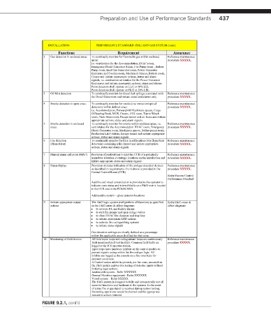
Preparation and Use of Performance Standards  437


                    INSTALLATION:      PERFORMANCE STANDARD: FIRE AND GAS SYSTEM (cont.)
                        Functions               Requirement           Assurance
                  2  Gas detection in enclosed areas.  To continually monitor for flammable gas within enclosed   Reference maintenance
                                     areas:                         procedure XXXXX.
                                     i.e. vent intakes for the Accommodation HVAC room,
                                     Emergency Diesel Generator Room, Fire Pump room , Ballast
                                     Pump room, Inert Gas Generator room, Power Generator
                                     Enclosure and Coolers room, Machinery Spaces, Battery room,
                                     Cranes and initiate appropriate actions, status and alarm
                                     signals, i.e. combustion air intakes for the Power Generator
                                     Enclosures and initiate appropriate actions, status and alarms
                                     Point detectors shall operate on LLG at 10% LEL
                                     Point detectors shall operate on HLG at 20% LEL
                  3  Oil Mist detection  To continually monitor for diesel fuel spillage associated with   Reference maintenance
                                     the Diesel Generators and initiate status and alarms only.  procedure XXXXX.
                  4  Smoke detection in open areas.  To continually monitor for smoke (via ionisation/optical   Reference maintenance
                                     detectors) within defined areas:  procedure XXXXX.
                                     i.e. Accommodation, Forward/Aft Machinery spaces, Cargo
                                     Offloading Deck, MCR, Cranes, CO2 room, Turret Winch
                                     room, Deck Store room, Escape tunnel and air locks and initiate
                                     appropriate actions, status and alarm signals.
                  5  Smoke detection in enclosed   To continually monitor for smoke within enclosed areas, i.e.  Reference maintenance
                     areas.          vent intakes for the Accommodation HVAC room, Emergency   procedure XXXXX.
                                     Diesel Generator room, Machinery spaces, Ballast pump room,
                                     Production Lab/Utilities, Escape tunnel and initiate appropriate
                                     actions, status and alarm signals.
                  6  Fire detection  To continually monitor for fires in all locations (via flame/heat   Reference maintenance
                     (Flame/Heat)    detection) containing a fire hazard and initiate appropriate   procedure XXXXX.
                                     actions, status and alarm signals.
                  7  Manualalarm call point (MAC)  Provision of pushbuttons to alert the CCR of a potentially   Reference maintenance
                                     hazardous situation at strategic locations on the installation and  procedure XXXXX.
                                     initiate appropriate status and alarm signals.
                  8  Status display  Provision of status indication of fire and gas detection devices   Reference maintenance
                                     as described in requirements 1 to 6 above is provided in the   procedure XXXXX.
                                     Central Control Room (CCR).
                                                                    Refer Process Control
                                                                    Performance Standard
                                     Audible and visual annunciation is provided to the operator to
                                     indicate zone status and internal faults on a F&G matrix located
                                     in the CCR and in the PCS/SCADA.
                                     Addressable system – gives detector locations
                  9  Initiate appropriate output   The F&G logic system shall perform all functions as specified   Refer F&G cause &
                     actions         on the F&G cause & effect diagrams:  effect diagrams
                                     ∑  to activate PA and facility alarms
                                     ∑  to start fire pumps and open deluge valves
                                     ∑  to close HVAC fire dampers and stop fans
                                     ∑  to initiate appropriate ESD actions
                                     ∑  to activate fire extinguishing systems
                                     ∑  to initiate status signals
                                     Gas detection settings are clearly defined as a percentage
                                     within the applicable cause & effect for that zone.
                  10  Monitoring of field devices  All field input loops and extinguishant loops are continuously   Reference maintenance
                                      fault monitored (self-test facility). Common field faults are   procedure XXXXX.
                                      logged at the ICS operator station.
                                      Input loops have hardware inhibits on the control module to
                                      prevent signals acting within the fire and gas logic. All
                                      inhibits are logged at the console on a fire zone basis for
                                      operator awareness.
                                      A Control action inhibit keyswitch, per fire zone, mounted on
                                      the F&G matrix enables live testing of detector inputs without
                                      initiating logic actions.
                                      Addressable system -Refer XXXXXX
                                      General Monitors equipment -Refer XXXXXX
                                      Vesselsystem – Refer XXXXX
                                      The F&G system is designed to fully and automatically test all
                                      essential functions and hardware in the systems. In the event
                                      of a true fire or gas signal is received during system testing,
                                      the testing operations would be aborted and the appropriate
                                      executive actions initiated.
                  FIGURE 9.2.1, cont’d