
Page 452 - Offshore Electrical Engineering Manual
P. 452
Preparation and Use of Performance Standards 439
(C)
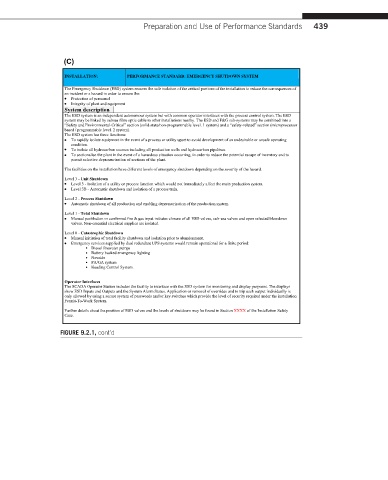
INSTALLATION: PERFORMANCE STANDARD: EMERGENCY SHUTDOWN SYSTEM
The Emergency Shutdown (ESD) system ensures the safe isolation of the critical portions of the installation to reduce the consequences of
an incident or a hazard in order to ensure the:
∑ Protection of personnel
∑ Integrity of plant and equipment
System description
The ESD system is an independent autonomous system but with common operator interfaces with the process controlsystem. The ESD
systemmay be linkedby subsea fibre optic cableto other installations nearby. The ESD and F&G sub-systems may be combined into a
“Safety and Environmental-Critical” section (solid-state/non-programmable level. 1 system) and a “safety-related” section (microprocessor
based / programmable level. 2 system).
The ESD system has three functions:
∑ To rapidly isolate equipment in the event of a process or utility upset to avoid development of an undesirable or unsafe operating
condition.
∑ To isolate all hydrocarbon sources including all production wells and hydrocarbon pipelines.
∑ To sectionalise the plant in the event of a hazardous situation occurring, in order to reduce the potential escape of inventory and to
permit selective depressurisation of sections of the plant.
The facilities on the installation have differentlevels of emergency shutdown depending on the severity of the hazard.
Level 3 - Unit Shutdown
∑ Level 3 - Isolation of a utility or process function which would not immediately affect the main production system.
∑ Level 3B - Automatic shutdown and isolation of a process train.
Level 2 - Process Shutdown
∑ Automatic shutdown of all production and enabling depressurisation of the production system.
Level 1 - Total Shutdown
∑ Manual pushbutton or confirmed fire & gas input initiates closure of all ESD valves, sub-sea valves and open selected blowdown
valves. Non-essential electrical supplies are isolated.
Level 0 - Catastrophic Shutdown
∑ Manual initiation of total facility shutdown and isolation prior to abandonment.
∑ Emergency services supplied by dual redundant UPS systems would remain operational for a finite period:
∑ Diesel firewater pumps
∑ Battery backed emergency lighting
∑ Navaids
∑ PA/GA system
∑ Heading Control System.
Operator Interfaces
The SCADA Operator Station includes the facility to interface with the ESD system for monitoring and display purposes. The displays
show ESD Inputs and Outputs and the System Alarm Status. Application or removal of overrides and to trip each output individually is
only allowed by using a secure system of passwords and/or key switches which provide the level of security required under the installation
Permit-To-Work System.
Further details about the position of ESD valves and the levels of shutdown may be found in Section XXXX of the InstallationSafety
Case.
FIGURE 9.2.1, cont’d