
Page 454 - Offshore Electrical Engineering Manual
P. 454
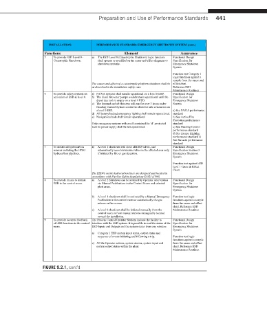
Preparation and Use of Performance Standards  441


                     INSTALLATION:      PERFORMANCE STANDARD: EMERGENCY SHUTDOWN SYSTEM (cont.)
                   Functions                       Element                Assurance
                   5   To provide ESD Level 0 -  a)  The ESD Level 0 (Catastrophic Shutdown) logic functions   Functional Design
                       Catastrophic Shutdown.  shall operate as specified on the cause and effect diagrams to   Specification for
                                        shut down systems.             Emergency Shutdown
                                                                       System
                                                                       Function test Category 1
                                                                       logic functions against a
                                                                       sample from the cause and
                                      The causes and effects of a catastrophic platform shutdown shall be  effect chart.
                                      as described in the installation safety case.  ReferenceESD
                                                                       Maintenance Routines
                   6   To provide safety systems on   a) PA/GA systems shall remain operational on a level 0 ESD.  Functional Design
                       activation of ESD at level 0.  b) The diesel firewater pumps would remain operational until the   Specification for
                                        diesel day tank is empty on a level 0 ESD.  Emergency Shutdown
                                      c) The forward and aft thrusters will run for over 3 hours under   System
                                        Heading Control System control to allow for safe evacuation on
                                        a level 0 ESD.                 a) See PA/GA performance
                                      d) All battery backed emergency lighting shall remain operational.  standard
                                      e) Navigational aids shall remain operational  b) See Active Fire
                                                                       Protection performance
                                      Only emergency systems with a self-contained Ex ‘d’ -protected   standard
                                      built-in power supply shall be left operational.  c) See Heading Control
                                                                       performance standard
                                                                       d) See Escape Lighting
                                                                       performance standard e)
                                                                       See Navaids performance
                                                                       standard
                   7   To isolate all hydrocarbon   a)  A level 1 shutdown will close all ESD valves, and   Functional Design
                       sources including the FPSO   automatically open blowdown valves in the affected area only   Specification Section 3
                       hydrocarbon pipelines.  if initiated by fire or gas detection.  Emergency Shutdown
                                                                       System
                                                                       Function test against ESD
                                                                       level 1 Cause & Effect
                                                                       Chart
                                      The ESDVs on the hydrocarbon lines are designed and located in
                                      accordance with Pipeline Safety Regulations SI 825 (1996)
                   8   To provide means to initiate   a)  A level 2 Shutdown can be initiated by Operator intervention   Functional Design
                       ESD in the control room.  via Manual Pushbuttons in the Control Room and selected   Specification for
                                        plant areas.                   Emergency Shutdown
                                                                       System
                                      b)  A level 1 shutdown shall be activated by a Manual Emergency  Function test logic
                                        Pushbutton in the control room or automatically if a gas   functions against a sample
                                        release or fire occurs.        from the cause and effect
                                                                       chart. ReferenceESD
                                      c)  A level 0 shutdown shall be initiated manually from the   Maintenance Routines.
                                        control room or from manual stations strategically located
                                        around the installation.
                   9   To provide accurate feedback   The Process Control Operator Stations include the facility to   Functional Design
                       of ESD functions to the control  interface with the ESD system. It is possible to read the status of the  Specification for
                       room.          ESD Inputs and Outputs and the system status from any window.  Emergency Shutdown
                                                                       System
                                      a)  Category 1 ESD system input status, output status and
                                        sequence of events initiating and following a trip.  Function test logic
                                                                       functions against a sample
                                      c) All the Operator actions, system alarms, system input and   from the cause and effect
                                        system output status within the plant.  chart. ReferenceESD
                                                                       Maintenance Routines.
                  FIGURE 9.2.1, cont’d