
Page 70 - Optofluidics Fundamentals, Devices, and Applications
P. 70
Optical Components Based on Dynamic Liquid-Liquid Interfaces 51
1.2
1 2 3 1.0
Intensity (a.u.) 0.8
10 mm 0.6
0.4
1 2 2 3 0.2
0.0
500 μm
400 450 500 550 600 650 700
Wavelength (nm)
(a) (b)
20 mm
n = 1.329
clad
1.5 n n clad = 1.455 n core = 1.455
= 1.479
Intensity (a.u.) 1.0
clad
0.5
500 μm 0.0
400 450 500 550 600 650 700
(c) Wavelength (nm)
(d)
2
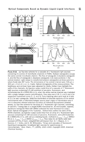
FIGURE 3-11 (a) Top-view scheme for a cascade of L fl uorescent light sources
consisting of a series of microfl uidic channels in PDMS. Multiple waveguides occupy
the same central microfl uidic channel. The fl ow of waveguide 2 displaces waveguide
3, and the fl ow of waveguide 1 displaces waveguide 2 at cross-junctions in the
central channel. Light output is transferred between waveguides at these junctions
where fl uids take 90° turns. The dimensions of the central channel were 130 μm ×
300 μm × 3 cm (h × w × l). Insets: Optical micrographs of the cross-junctions. The
brightness and contrast have been adjusted for clarity. Dotted lines highlight the
2
walls of the channels. (b) Spectral output (solid line) of a cascade of L fl uorescent
light sources containing 0.5 mM solutions of perylene, fl uorescein, and
sulforhodamine B in DMSO/EG (1:1), when the entire central channel was irradiated
with a single halogen source (uncollimated). Flow rates were 0.8, 2, and 5 mL/h for
respective fl uorescent cores (1, 2, and 3). Core/cladding rates were kept at a ratio
of 2:1 for each waveguide. Selective illumination of discrete sections of the central
microchannel with a collimated halogen source (each region of illumination was 4
mm in diameter) allowed selective excitation of individual fl uorophores (shaded
2
areas). (c) Top-view scheme for the array of L fl uorescent light sources, consisting
of parallel L waveguides in a single PDMS microchannel. An end-coupled, tapered,
2
liquid-core waveguide fi lled with DMSO collected the total fl uorescence output.
Inset: Optical micrograph of the T-junction. Dotted lines outline the walls of the
2
PDMS channels. (d) Spectral output (solid line) from an array of L fl uorescent light
sources containing 0.5 mM solutions of perylene, fl uorescein, and sulforhodamine
B in DMSO/EG (1:1), with various cladding liquids: methanol (n < n ); DMSO/
cladding core
EG (1:1, n = n ); DMSO (n > n ). Flow rates for all inputs were held
cladding core cladding core
constant at 4 mL/h each. (Adapted with permission from B. T. Mayers, D. V.
Vezenov, V. I. Vullev, and G. M. Whitesides, “Arrays and cascades of fluorescent
liquid-liquid waveguides: broadband light sources for spectroscopy in
microchannels,” Anal. Chem., 77, (2005), 1310–1316. Copyright 2005. American
Chemical Society.)