
Page 67 - Optofluidics Fundamentals, Devices, and Applications
P. 67
48 Cha pte r T h ree
by filling two separate channels with black ink. For applications that
require higher intensity at the focus, the aperture can be removed. In
order to visualize the optical path, a beam-tracing chamber filled flu-
orescent dyes (2.5 μM rhodamine 640 perchlorate in ethylene glycol)
is incorporated behind the L lens.
2
Characterization
2
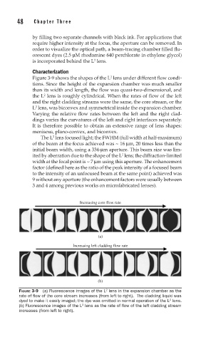
Figure 3-9 shows the shapes of the L lens under different flow condi-
tions. Since the height of the expansion chamber was much smaller
than its width and length, the flow was quasi-two-dimensional, and
the L lens is roughly cylindrical. When the rates of flow of the left
2
and the right cladding streams were the same, the core stream, or the
L lens, was biconvex and symmetrical inside the expansion chamber.
2
Varying the relative flow rates between the left and the right clad-
dings varies the curvatures of the left and right interfaces separately.
It is therefore possible to obtain an extensive range of lens shapes:
meniscus, plano-convex, and biconvex.
The L lens focused light; the FWHM (full width at half-maximum)
2
of the beam at the focus achieved was ~ 16 μm, 20 times less than the
initial beam width, using a 334-μm aperture. This beam size was lim-
2
ited by aberration due to the shape of the L lens; the diffraction-limited
width at the focal point is ~ 7 μm using this aperture. The enhancement
factor (defined here as the ratio of the peak intensity of a focused beam
to the intensity of an unfocused beam at the same point) achieved was
9 without any aperture (the enhancement factors were usually between
3 and 4 among previous works on microfabricated lenses).
Increasing core flow rate
(a)
Increasing left cladding flow rate
(b)
2
FIGURE 3-9 (a) Fluorescence images of the L lens in the expansion chamber as the
rate of fl ow of the core stream increases (from left to right). The cladding liquid was
2
dyed to make it easily imaged; the dye was omitted in normal operation of the L lens.
(b) Fluorescence images of the L lens as the rate of fl ow of the left cladding stream
2
increases (from left to right).