
Page 66 - Optofluidics Fundamentals, Devices, and Applications
P. 66
Optical Components Based on Dynamic Liquid-Liquid Interfaces 47
central (“core”) stream is higher than the index of the sandwiching (“clad-
ding”) streams [2]. The streams enter a microchannel containing an
“expansion chamber”—a region in which the width of the channel expands
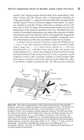
laterally. Figure 3-8 shows a schematic diagram of this system. The expan-
sion chamber is typically 10 times wider than its entrance and exit. For
some rates of flow, the shape of the interface between the core and clad-
ding streams in the expansion chamber is biconvex. This fluidic biconvex
structure focuses light propagating in the plane of the expansion chamber,
and perpendicular to the direction of flow of the liquids. By changing the
relative rates of flow of the three streams, it is possible to change the curva-
ture of the interface and thus the focal distance of the lens in real time.
To observe the focal point of the lens within the PDMS device
(~ 2 cm × 2 cm), the contrast in refractive indices should be suffi-
ciently large (Δn > ~ 0.1). Here, benzyl alcohol (n = 1.54) and
d d
benzothiazole (n = 1.64) have been used as the core liquid; and
d
trifluoroethanol (n = 1.29) as the cladding. To facilitate beam tracing
d
and determination of the focal point of the L lens, an aperture can be
2
included in front of the expansion chamber to block incident light
from regions of the lens close to the inlet and outlet where the radius
of curvature is highly nonuniform (Fig. 3-8). The aperture is formed
z
y Outline of Core
2
x L lens Cladding
Cladding
Beam-tracing
chamber Dye out
Xc Expansion chamber
Optical fiber
R curvature
ya
Outline of ye
Dye the beam
in Dye out Light from
off-chip laser
h Xe Aperture
x 1
To outlet x 0
FIGURE 3-8 Schematic representation of the experimental setup for focusing light
exiting an optical fi ber through the liquid-core liquid-cladding (L ) lens. The aperture is
2
formed by two channels fi lled with black ink after fabrication. The channel for the
2
formation of the L lens contains a square expansion chamber. The solid lines show
the walls of the channel, and the dashed lines show the interfaces between the core
and the cladding streams. R curvature is the radius of curvature of this interface. The
height (h) of the channel is about 100 mm. The beam-tracing chamber behind the L 2
lens is fi lled with solution of a fl uorescent dye (2.5 μm Rhodamine 640 perchlorate in
ethylene glycol) to make the optical path visible. (S. K. Y. Tang, C. A. Stan, and G. M.
Whitesides, “Dynamically reconfigurable liquid-core liquid-cladding lens in a
microfluidic channel,” Lab Chip, 8, (2008), 395–401. Reproduced by permission of
the Royal Society of Chemistry.)