
Page 64 - Optofluidics Fundamentals, Devices, and Applications
P. 64
Optical Components Based on Dynamic Liquid-Liquid Interfaces 45
1.4 CG IG
1.2
150 μm
1.0
I CG /I IG 0.8 CG IG
0.6
0.4
0.2
0 CG IG
1.5 2.0 2.5 3.0 3.5 4.0 4.5 5.0
Width of center cladding layer (μm)
(b)
(i) 100
Intensity (a.u.) 50 125 μm
0
–375 –250 –125 0 125 250 375
Light input/ Distance from center of channel (μm) Light outputs/
flow output
(ii) 20 flow inputs
Distance from center of channel (μm) –10 0
10
–20
0 2 4 6 8 10
Distance along length of channel (mm)
(c)
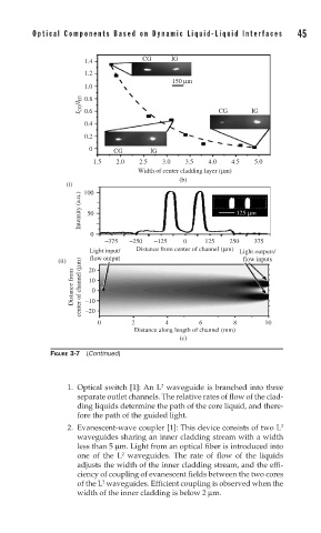
FIGURE 3-7 (Continued)
2
1. Optical switch [1]: An L waveguide is branched into three
separate outlet channels. The relative rates of flow of the clad-
ding liquids determine the path of the core liquid, and there-
fore the path of the guided light.
2. Evanescent-wave coupler [1]: This device consists of two L 2
waveguides sharing an inner cladding stream with a width
less than 5 μm. Light from an optical fiber is introduced into
2
one of the L waveguides. The rate of flow of the liquids
adjusts the width of the inner cladding stream, and the effi-
ciency of coupling of evanescent fields between the two cores
2
of the L waveguides. Efficient coupling is observed when the
width of the inner cladding is below 2 μm.