
Page 69 - Optofluidics Fundamentals, Devices, and Applications
P. 69
50 Cha pte r T h ree
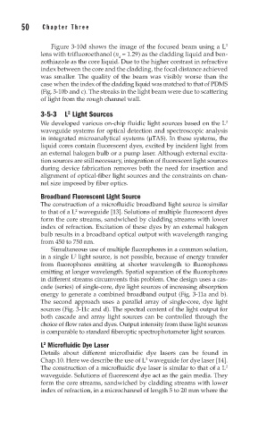
Figure 3-10d shows the image of the focused beam using a L 2
lens with trifluoroethanol (n = 1.29) as the cladding liquid and ben-
d
zothiazole as the core liquid. Due to the higher contrast in refractive
index between the core and the cladding, the focal distance achieved
was smaller. The quality of the beam was visibly worse than the
case when the index of the cladding liquid was matched to that of PDMS
(Fig. 3-10b and c). The streaks in the light beam were due to scattering
of light from the rough channel wall.
2
3-5-3 L Light Sources
We developed various on-chip fluidic light sources based on the L 2
waveguide systems for optical detection and spectroscopic analysis
in integrated microanalytical systems (μTAS). In these systems, the
liquid cores contain fluorescent dyes, excited by incident light from
an external halogen bulb or a pump laser. Although external excita-
tion sources are still necessary, integration of fluorescent light sources
during device fabrication removes both the need for insertion and
alignment of optical-fiber light sources and the constraints on chan-
nel size imposed by fiber optics.
Broadband Fluorescent Light Source
The construction of a microfluidic broadband light source is similar
to that of a L waveguide [13]. Solutions of multiple fluorescent dyes
2
form the core streams, sandwiched by cladding streams with lower
index of refraction. Excitation of these dyes by an external halogen
bulb results in a broadband optical output with wavelength ranging
from 450 to 750 nm.
Simultaneous use of multiple fluorophores in a common solution,
2
in a single L light source, is not possible, because of energy transfer
from fluorophores emitting at shorter wavelength to fluorophores
emitting at longer wavelength. Spatial separation of the fluorophores
in different streams circumvents this problem. One design uses a cas-
cade (series) of single-core, dye light sources of increasing absorption
energy to generate a combined broadband output (Fig. 3-11a and b).
The second approach uses a parallel array of single-core, dye light
sources (Fig. 3-11c and d). The spectral content of the light output for
both cascade and array light sources can be controlled through the
choice of flow rates and dyes. Output intensity from these light sources
is comparable to standard fiberoptic spectrophotometer light sources.
2
L Microfluidic Dye Laser
Details about different microfluidic dye lasers can be found in
Chap.10. Here we describe the use of L waveguide for dye laser [14].
2
The construction of a microfluidic dye laser is similar to that of a L 2
waveguide. Solutions of fluorescent dye act as the gain media. They
form the core streams, sandwiched by cladding streams with lower
index of refraction, in a microchannel of length 5 to 20 mm where the