
Page 61 - Optofluidics Fundamentals, Devices, and Applications
P. 61
42 Cha pte r T h ree
1.50
1.48 z
0.1 mL/h 1.46 z z 1 2
Refractive index 1.42 3
1.44
1.40
x 1.38
z 1.36
1.34
z 1 z 2 z 3 –50 –25 0 25 50
(a) Distance (μm)
(b)
1.50
1.48
20 mL/h 1.46 z z 1 2
Refractive index 1.44 z 3
1.42
1.40
1.38
1.36
1.34
z 1 z 2 z 3 –50 –25 0 25 50
(c) Distance (μm)
(d)
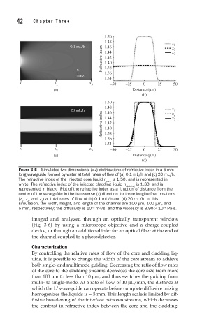
FIGURE 3-5 Simulated two-dimensional (x-z) distributions of refractive index in a 5-mm-
long waveguide formed by water at total rates of fl ow of (a) 0.1 mL/h and (c) 20 mL/h.
The refractive index of the injected core liquid n is 1.50, and is represented in
core
white. The refractive index of the injected cladding liquid n is 1.33, and is
cladding
represented in black. Plot of the refractive index as a function of distance from the
center of the waveguide in the transverse (x) direction for three longitudinal positions
(z , z , and z ) at total rates of fl ow of (b) 0.1 mL/h and (d) 20 mL/h. In this
1 2 3
simulation, the width, height, and length of the channel are 100 μm, 100 μm, and
2
−4
5 mm, respectively; the diffusivity is 10 m /s, and the viscosity is 8.90 × 10 Pa·s.
−9
imaged and analyzed through an optically transparent window
(Fig. 3-6) by using a microscope objective and a charge-coupled
device, or through an additional inlet for an optical fiber at the end of
the channel coupled to a photodetector.
Characterization
By controlling the relative rates of flow of the core and cladding liq-
uids, it is possible to change the width of the core stream to achieve
both single- and multimode guiding. Decreasing the ratio of flow rates
of the core to the cladding streams decreases the core size from more
than 100 μm to less than 10 μm, and thus switches the guiding from
multi- to single-mode. At a rate of flow of 10 μL/min, the distance at
2
which the L waveguide can operate before complete diffusive mixing
homogenizes the liquids is ~ 5 mm. This length scale is limited by dif-
fusive broadening of the interface between streams, which decreases
the contrast in refractive index between the core and the cladding.