
Page 169 - Organic Electronics in Sensors and Biotechnology
P. 169
146 Cha pte r F o u r
10 4 10 2 10 0 10 4 10 2 10 0
10 4 Penetration depth (μm) ohne 10 4 10 4 Penetration depth (μm) ohne 10 4
50 μm 50 μm
175 μm 175 μm
10 2 575 μm 10 2 10 2 575 μm 10 2
Temperature lift (K) 10 –2 10 0 Temperature lift (K) 10 –2 10 0
1 mm
1 mm
10 mm
10 mm
10 0
10 0
10 –2
10 –2
10 –4 10 –4 10 –4 10 –4
Temperature lift with silicon substrate Temperature lift with glass substrate
10 –4 10 –2 10 0 10 2 10 4 10 6 10 –4 10 –2 10 0 10 2 10 4 10 6
Frequency (Hz) Frequency (Hz)
(a) (b)
10 4 10 2 10 0
Penetration depth (μm) ohne
50 μm
10 2 175 μm 10 2
575 μm
Temperature lift (K) 10 –2 10 mm 10 0
1 mm
10 0
10 –2
10 –4 10 –4
Temperature lift with Melinex substrate
10 –4 10 –2 10 0 10 2 10 4 10 6
Frequency (Hz)
(c)
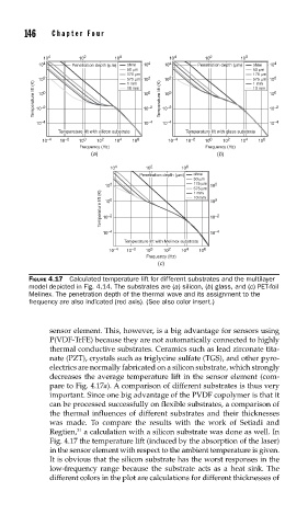
FIGURE 4.17 Calculated temperature lift for different substrates and the multilayer
model depicted in Fig. 4.14. The substrates are (a) silicon, (b) glass, and (c) PET-foil
Melinex. The penetration depth of the thermal wave and its assignment to the
frequency are also indicated (red axis). (See also color insert.)
sensor element. This, however, is a big advantage for sensors using
P(VDF-TrFE) because they are not automatically connected to highly
thermal conductive substrates. Ceramics such as lead zirconate tita-
nate (PZT), crystals such as triglycine sulfate (TGS), and other pyro-
electrics are normally fabricated on a silicon substrate, which strongly
decreases the average temperature lift in the sensor element (com-
pare to Fig. 4.17a). A comparison of different substrates is thus very
important. Since one big advantage of the PVDF copolymer is that it
can be processed successfully on flexible substrates, a comparison of
the thermal influences of different substrates and their thicknesses
was made. To compare the results with the work of Setiadi and
31
Regtien, a calculation with a silicon substrate was done as well. In
Fig. 4.17 the temperature lift (induced by the absorption of the laser)
in the sensor element with respect to the ambient temperature is given.
It is obvious that the silicon substrate has the worst responses in the
low-frequency range because the substrate acts as a heat sink. The
different colors in the plot are calculations for different thicknesses of