
Page 171 - Organic Electronics in Sensors and Biotechnology
P. 171
148 Cha pte r F o u r
Current response Voltage response
ohne ohne
50 μm 10 0 50 μm
175 μm 175 μm
575 μm 575 μm
10 –8 1 mm 10 –1 1 mm
10 mm 10 mm
Current (A) 10 –9 Voltage (V) 10 –2
10 –3
10 –4
10 –10
10 –5
10 –4 10 –2 10 0 10 2 10 4 10 6 10 –4 10 –2 10 0 10 2 10 4 10 6
Frequency (Hz) Frequency (Hz)
(a)
Current response Voltage response
ohne ohne
50 μm 10 0 50 μm
175 μm 175 μm
10 –8 575 μm 575 μm
1 mm 10 –1 1 mm
10 mm 10 mm
Current (A) 10 –9 Voltage (V) 10 –2
10 –3
10 –4
10 –10
10 –5
10 –4 10 –2 10 0 10 2 10 4 10 6 10 –4 10 –2 10 0 10 2 10 4 10 6
Frequency (Hz) Frequency (Hz)
(b)
Current response Voltage response
ohne ohne
50 μm 10 0 50 μm
175 μm 175 μm
575 μm 575 μm
10 –8 1 mm 10 –1 1 mm
10 mm 10 mm
Current (A) 10 –9 Voltage (V) 10 –2
10 –3
10 –4
10 –10
10 –5
10 –4 10 –2 10 0 10 2 10 4 10 6 10 –4 10 –2 10 0 10 2 10 4 10 6
Frequency (Hz) Frequency (Hz)
(c)
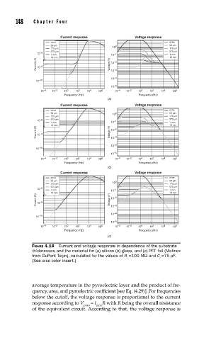
FIGURE 4.18 Current and voltage response in dependence of the substrate
thicknesses and the material for (a) silicon (b) glass, and (c) PET foil (Melinex
from DuPont Teijin), calculated for the values of R =100 MΩ and C =75 pF.
i i
(See also color insert.)
average temperature in the pyroelectric layer and the product of fre-
quency, area, and pyroelectric coefficient [see Eq. (4.29)]. For frequencies
below the cutoff, the voltage response is proportional to the current
response according to V = I R with R being the overall resistance
pyro pyro
of the equivalent circuit. According to that, the voltage response is