
Page 255 - Organic Electronics in Sensors and Biotechnology
P. 255
232 Cha pte r S i x
inverting input, this leads to positive feedback; in consequence, any
high-frequency noise that contaminates the signal can force the ampli-
fier into instability (sustained oscillations). The usual solution is to add
a feedback capacitance in parallel with the feedback resistance, which
reduces the gain at high frequencies (since the capacitor behaves as a
low-impedance short) and so suppresses the high-frequency noise
components, albeit at the expense of signal bandwidth. Stability issues
can often be solved by careful amplifier selection, some amplifiers
being more susceptible to oscillations than others.
6.5.2 The Charge Integrator
In situations where the photocurrent is significantly less than 1 pA, it
may not be possible to achieve sufficient gain using a single-stage tran-
simpedance circuit since 1 GΩ is normally considered the highest prac-
tical value for the feedback resistor (1 GΩ × 1 pA = 1 mV). One solution
is to use a two-stage amplifier, comprising an initial current-to-voltage
stage followed immediately by a voltage amplification stage. This has
the advantage of providing improved bandwidth since substantially
lower gains can be employed at each stage. However, the increased
bandwidth comes at the expense of increased noise: if the feedback
resistor at the current-to-voltage stage is reduced by a factor α, the sig-
nal is reduced by the same factor α, but from Eq. (6.33) the thermal
noise is reduced only by a factor α . To achieve the same overall sig-
nal gain, the voltage gain at the second stage must be equal to α so the
noise contribution from the first feedback resistor is increased by a fac-
tor 1/ α × α = α compared to the single-stage process.
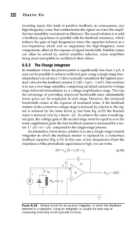
An alternative, lower-noise, solution is to use a (single-stage) current
integrator in which the feedback resistor is replaced by a (noise-free)
feedback capacitor (Fig. 6.19). In this case, at low frequencies where the
impedance of the photodiode capacitance is high, we can write:
it () = i () + i t () − i −
t
sh f B (6.58)
i f C f
–
i sh i – ~ ~ –Q/C
i B V out f
+
R sh C
FIGURE 6.19 Simple circuit for an op-amp integrator, in which the feedback
element is a capacitor. Using an integrator is usually the best way of
measuring extremely small (sub-pA) currents.