
Page 258 - Organic Electronics in Sensors and Biotechnology
P. 258
An Intr oduction to Or ganic Photodetectors 235
which would put organic devices on a par with standard pn-type Si
photodiodes; achieving substantially greater reductions, although
possible, will probably prove challenging with existing materials
systems.
Anyway, regardless of what might be possible in the future,
organic photodiodes in use today have typical capacitance densities
2
of a few hundred pF/mm . In practical terms this means they are 10
to 100 times slower than Si photodiodes and very much slower than
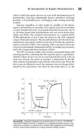
APDs and PMTs. The transient characteristics of a typical P3HT:
2
PCBM photodiode of area 9 mm are shown in Fig. 6.20, obtained
using a 50 Ω load resistance. The rise and fall times are 0.45 and 0.5 μs,
respectively from which it follows from Eq. (6.31) that the cutoff fre-
quency is about 0.7 MHz. This compares with a rise time of 50 ns for
2
a typical Si photodiode (Hamamatsu S6931) of similar area (6.6 mm )
and with a comparable load resistance (100 Ω).
The OPV transients exhibit characteristic exponential charge and
discharge profiles, indicating that the response speed is capacitance-
limited in these devices (see fits to experimental data in Fig. 6.20). In
large-area devices, the speed of response is determined by the RC
time constant and therefore scales linearly with device area. When the
device area is sufficiently small, the response time is no longer deter-
mined by the capacitance, but rather by the transit time τ, i.e., the
1.2
Fit: RC = 0.20 μs
1
Excitation
light
0.8
Signal (AU) 0.6 Photodiode
0.4
response
0.2
0
Fit: RC = 0.23 μs
–0.2
0 1 2 3 4 5 6
Time (μs)
FIGURE 6.20 Transient response curve (black line) of a 9 mm ITO/PEDOT:
2
PSS/P3HT:PCBM/Al device in response to a stepped excitation source. The
dotted line indicates a numerical fi t to exponential charging and discharging
curves. (Data kindly provided by X. Wang, Imperial College London.)