
Page 116 - PDA Robotics Using Your Personal Digital Assistant to Control Your Robot
P. 116
PDA 05 5/30/03 11:35 AM Page 92
Port/Peripheral Select (2) PDA Robotics
Peripheral Data Out
0 VDD
Data Bus
D Q
WR P I/O (1)
Port 1 pin
CK Q
Data Latch
D Q
WR
TRIS Q
CK N
TRIS Latch
VSS
RD
TRIS
Schmitt
Trigger
Peripheral
OE (3) Q D
Schmitt
Trigger
EN
RD with
Port 0 SMBus
levels
SSPI Input
1
CKE
SSPSTAT<6>
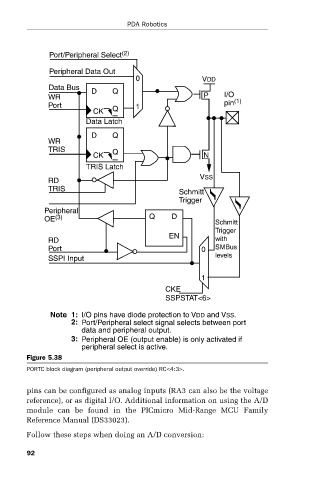
Note 1: I/O pins have diode protection to VDD and VSS.
2: Port/Peripheral select signal selects between port
data and peripheral output.
3: Peripheral OE (output enable) is only activated if
peripheral select is active.
Figure 5.38
PORTC block diagram (peripheral output override) RC<4:3>.
pins can be configured as analog inputs (RA3 can also be the voltage
reference), or as digital I/O. Additional information on using the A/D
module can be found in the PICmicro Mid-Range MCU Family
Reference Manual (DS33023).
Follow these steps when doing an A/D conversion:
92