
Page 113 - PDA Robotics Using Your Personal Digital Assistant to Control Your Robot
P. 113
PDA 05 5/30/03 11:35 AM Page 89
Chapter 5 / The Electronics
VDD
RBPU (2) Weak
P
Pull-up
Data Latch
Data Bus
D Q
I/O
WR Port (1)
CK pin
TRIS Latch
D Q
WR TRIS TTL
CK Input
Buffer ST
Buffer
RD TRIS
Latch
Q D
RD Port
EN Q1
Set RBIF
Q D
From other RD Port
RB7:RB4 pins EN
Q3
RB7:RB6
In Serial Programming Mode
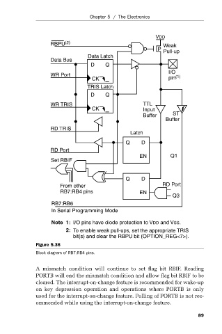
Note 1: I/O pins have diode protection to VDD and VSS.
2: To enable weak pull-ups, set the appropriate TRIS
bit(s) and clear the RBPU bit (OPTION_REG<7>).
Figure 5.36
Block diagram of RB7:RB4 pins.
A mismatch condition will continue to set flag bit RBIF. Reading
PORTB will end the mismatch condition and allow flag bit RBIF to be
cleared. The interrupt-on-change feature is recommended for wake-up
on key depression operation and operations where PORTB is only
used for the interrupt-on-change feature. Polling of PORTB is not rec-
ommended while using the interrupt-on-change feature.
89