
Page 298 - Petroleum and Gas Field Processing
P. 298
membrane and permeate across the membrane under the partial pressure
gradient across the membrane wall. The rate of permeation of gas A(q A )
can be expressed as
PM
q A ¼ A m P A ð21Þ
t
where PM is the gas permeability in the membrane, A m and t are the
surface area and thickness of the membrane, respectively, and P A is the
partial pressure of gas A across the membrane.
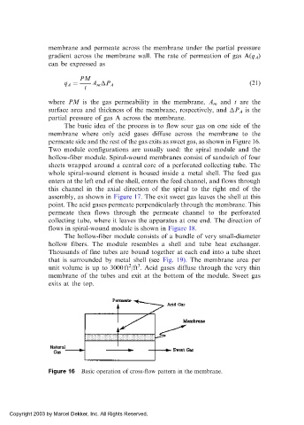
The basic idea of the process is to flow sour gas on one side of the
membrane where only acid gases diffuse across the membrane to the
permeate side and the rest of the gas exits as sweet gas, as shown in Figure 16.
Two module configurations are usually used: the spiral module and the
hollow-fiber module. Spiral-wound membranes consist of sandwich of four
sheets wrapped around a central core of a perforated collecting tube. The
whole spiral-wound element is housed inside a metal shell. The feed gas
enters at the left end of the shell, enters the feed channel, and flows through
this channel in the axial direction of the spiral to the right end of the
assembly, as shown in Figure 17. The exit sweet gas leaves the shell at this
point. The acid gases permeate perpendicularly through the membrane. This
permeate then flows through the permeate channel to the perforated
collecting tube, where it leaves the apparatus at one end. The direction of
flows in spiral-wound module is shown in Figure 18.
The hollow-fiber module consists of a bundle of very small-diameter
hollow fibers. The module resembles a shell and tube heat exchanger.
Thousands of fine tubes are bound together at each end into a tube sheet
that is surrounded by metal shell (see Fig. 19). The membrane area per
2
3
unit volume is up to 3000 ft /ft . Acid gases diffuse through the very thin
membrane of the tubes and exit at the bottom of the module. Sweet gas
exits at the top.
Figure 16 Basic operation of cross-flow pattern in the membrane.
Copyright 2003 by Marcel Dekker, Inc. All Rights Reserved.