
Page 171 - Phase Space Optics Fundamentals and Applications
P. 171
152 Chapter Four
Object
y Achromatic
lens Zone
x Plate Achromatic
Fresnel pattern
y
x
R 1
R o
R 2
l
f
d'
o
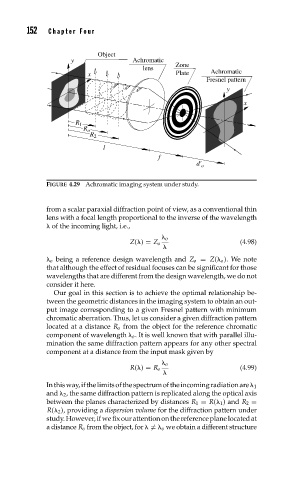
FIGURE 4.29 Achromatic imaging system under study.
from a scalar paraxial diffraction point of view, as a conventional thin
lens with a focal length proportional to the inverse of the wavelength
of the incoming light, i.e.,
o
Z( ) = Z o (4.98)
o being a reference design wavelength and Z o = Z( o ). We note
that although the effect of residual focuses can be significant for those
wavelengths that are different from the design wavelength, we do not
consider it here.
Our goal in this section is to achieve the optimal relationship be-
tween the geometric distances in the imaging system to obtain an out-
put image corresponding to a given Fresnel pattern with minimum
chromatic aberration. Thus, let us consider a given diffraction pattern
located at a distance R o from the object for the reference chromatic
component of wavelength o . It is well known that with parallel illu-
mination the same diffraction pattern appears for any other spectral
component at a distance from the input mask given by
o
R( ) = R o (4.99)
Inthisway,ifthelimitsofthespectrumoftheincomingradiationare 1
and 2 , the same diffraction pattern is replicated along the optical axis
between the planes characterized by distances R 1 = R( 1 ) and R 2 =
R( 2 ), providing a dispersion volume for the diffraction pattern under
study.However,ifwefixourattentiononthereferenceplanelocatedat
a distance R o from the object, for = o we obtain a different structure