
Page 170 - Phase Space Optics Fundamentals and Applications
P. 170
The Radon-Wigner Transform 151
1.0 1.0
Axial illuminance (a.u.) 0.5 Chromaticity coordinate y(W 20 ) 0.5
0.0 0.0
–1500 –1000 –500 0 500 1000 0.0 0.4 0.8
Defocus parameter: W 20 (nm) Chromaticity coordinate x(W 20 )
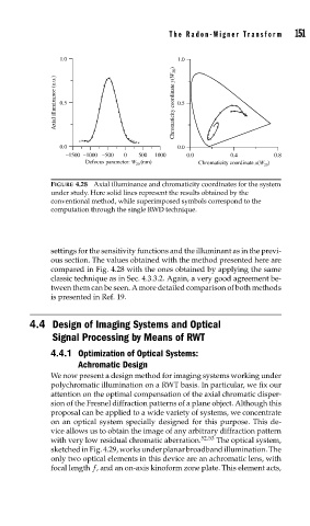
FIGURE 4.28 Axial illuminance and chromaticity coordinates for the system
under study. Here solid lines represent the results obtained by the
conventional method, while superimposed symbols correspond to the
computation through the single RWD technique.
settings for the sensitivity functions and the illuminant as in the previ-
ous section. The values obtained with the method presented here are
compared in Fig. 4.28 with the ones obtained by applying the same
classic technique as in Sec. 4.3.3.2. Again, a very good agreement be-
tween them can be seen. A more detailed comparison of both methods
is presented in Ref. 19.
4.4 Design of Imaging Systems and Optical
Signal Processing by Means of RWT
4.4.1 Optimization of Optical Systems:
Achromatic Design
We now present a design method for imaging systems working under
polychromatic illumination on a RWT basis. In particular, we fix our
attention on the optimal compensation of the axial chromatic disper-
sion of the Fresnel diffraction patterns of a plane object. Although this
proposal can be applied to a wide variety of systems, we concentrate
on an optical system specially designed for this purpose. This de-
vice allows us to obtain the image of any arbitrary diffraction pattern
with very low residual chromatic aberration. 52,53 The optical system,
sketched in Fig. 4.29, works under planar broadband illumination. The
only two optical elements in this device are an achromatic lens, with
focal length f, and an on-axis kinoform zone plate. This element acts,