
Page 114 - Photodetection and Measurement - Maximizing Performance in Optical Systems
P. 114
System Noise and Synchronous Detection
System Noise and Synchronous Detection 107
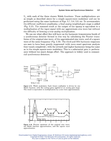
V in with each of the three chosen Walsh functions. These multiplications are
as simple as described above for a simple square-wave modulator and can be
performed using the same hardware of Figs. 5.7, 5.8, 5.9, etc. To accommodate
the different coefficient amplitudes, a final analog weighted-gain stage is added
(Fig. 5.15). The summed result at the output of the opamp is equivalent to a
multiplication of the input signal with our approximate sine wave but without
the difficulty of forming a true analog multiplication.
We can see what effect this will have on the harmonic transmission bands of
a synchronous detector formed in this way by calculating the Fourier trans-
forms of the original sine wave, of the approximated sine wave, and of a square
wave of the same frequency (Fig. 5.16). The third and fifth harmonic responses
are seen to have been greatly suppressed (with more exact spectrum analysis
they vanish completely), with the seventh and higher harmonics being the same
as in the simple square-wave modulator. This is a substantial gain in perform-
ance without too much design effort. The approach is widely used in commer-
cial synchronous detectors.
1.59R 10R
Noisy X ± 1
input WAL(1,16)
signal - R Demod.
X ± 1 + output
8.0R +
C -
WAL(3,16) RC filter
X ± 1
3.85R
WAL(7,16)
Figure 5.15 Walsh modulator. Each binary multiplier is driven by one
Walsh function, with the scaling gains applied in an analog gain stage.
The result is equivalent to multiplication by a sine wave approximation.
6
Amplitudes 4 Square wave
2
Walsh approx.
Sine wave
0
0 1 2 3 4 5 6 7
Figure 5.16 Fourier spectrum of the original sine wave,
the Walsh function approximation, and the square wave
approximation.
Downloaded from Digital Engineering Library @ McGraw-Hill (www.digitalengineeringlibrary.com)
Copyright © 2004 The McGraw-Hill Companies. All rights reserved.
Any use is subject to the Terms of Use as given at the website.