
Page 119 - Photodetection and Measurement - Maximizing Performance in Optical Systems
P. 119
System Noise and Synchronous Detection
112 Chapter Five
Lock-in amplifier
RC time
Multiplier constant Scope
x Voltage
Power display
supply
Signal Reference
input clock input
Transimpedance
receiver
Adjustable generator
-
+
Photodiode
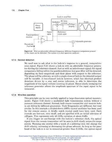
Figure 5.21 With an adjustable reference frequency, different frequency components present
in the input can be detected. The system is a slow spectrum analyzer.
5.7.3 General detection
We need now to ask what is the lock-in’s response to a general, nonsynchro-
nous signal. Figure 5.21 shows a lock-in with an adjustable frequency genera-
tor driving the reference channel. Just as with an interference signal, the signal
components falling within the postdemodulation low-pass filter will be detected,
depending on their magnitude and their phase with respect to the reference.
The phase will be arbitrary, so with a single channel lock-in the detected output
will be variable. A two-channel lock-in however, which has identical product
detectors driven by a sine and cosine reference, is able to determine the
magnitude of the signal without knowing its phase. Hence slowly sweeping the
reference generator allows the amplitude spectrum of the input signal to be
measured.
5.7.4Wire-free operation
This principle can be very usefully applied to large-dimension optical measure-
ments. Figure 5.22 shows a modulated light transmission system without a
common reference channel. Instead, both source transmitter and receiver lock-
in are driven by different generators. Their frequencies are different, but very
similar. In this example a divided-down 3MHz crystal oscillator has been used
for the remote source. A 32kHz watch crystal could have been used. Such
crystals are low-cost, very small, and are specified with an initial tolerance of
±20ppm. This represents only ±0.16Hz variation at about 8kHz.
If you trigger an oscilloscope with the lock-in’s reference clock, the optical
signal from the remote transmitter will be seen to drift slowly across the scope
screen. Warming one crystal with a touch of a soldering iron will change the
drift velocity, increasing or decreasing the phase advance. As long as the pass-
band of the lock-in is set to somewhat greater than 0.16Hz, the optical signal
Downloaded from Digital Engineering Library @ McGraw-Hill (www.digitalengineeringlibrary.com)
Copyright © 2004 The McGraw-Hill Companies. All rights reserved.
Any use is subject to the Terms of Use as given at the website.