
Page 120 - Photodetection and Measurement - Maximizing Performance in Optical Systems
P. 120
System Noise and Synchronous Detection
System Noise and Synchronous Detection 113
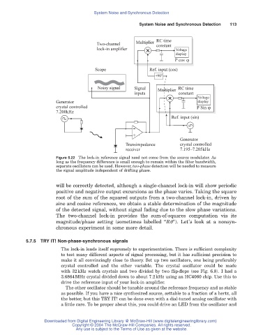
Multiplier RC time
Two-channel constant
lock-in amplifier Voltage
display
P cos j
Scope Ref. input (cos)
+90°
Noisy signal Signal Multiplier RC time
inputs constant
Voltage
Generator display
crystal controlled P Sin j
7.200kHz
Ref. input (sin)
-
Generator
+
Transimpedance crystal controlled
receiver 7.195–7.205kHz
Figure 5.22 The lock-in reference signal need not come from the source modulator. As
long as the frequency difference is small enough to remain within the filter bandwidth,
separate oscillators can be used. However, two-phase detection will be needed to measure
the signal amplitude independent of drifting phase.
will be correctly detected, although a single-channel lock-in will show periodic
positive and negative output excursions as the phase varies. Taking the square
root of the sum of the squared outputs from a two-channel lock-in, driven by
sine and cosine references, we obtain a stable determination of the magnitude
of the detected signal, without signal fading due to the slow phase variations.
The two-channel lock-in provides the sum-of-squares computation via its
magnitude/phase setting (sometimes labelled “Rq”). Let’s look at a nonsyn-
chronous experiment in some more detail.
5.7.5TRY IT! Non-phase-synchronous signals
The lock-in lends itself supremely to experimentation. There is sufficient complexity
to test many different aspects of signal processing, but it has sufficient precision to
make it all convincingly close to theory. Set up two oscillators, one being preferably
crystal controlled and the other variable. The crystal oscillator could be made
with 32kHz watch crystals and two divided by two flip-flops (see Fig. 6.8). I had a
3.6864MHz crystal divided down to about 7.2kHz using an HC4060 chip. Use this to
drive the reference input of your lock-in amplifier.
The other oscillator should be tunable around the reference frequency and as stable
as possible. If you have a nice synthesized source, settable to a fraction of a hertz, all
the better, but this TRY IT! can be done even with a dial-tuned analog oscillator with
a little care. To be proper about this, you could drive an LED from the oscillator and
Downloaded from Digital Engineering Library @ McGraw-Hill (www.digitalengineeringlibrary.com)
Copyright © 2004 The McGraw-Hill Companies. All rights reserved.
Any use is subject to the Terms of Use as given at the website.