
Page 123 - Photodetection and Measurement - Maximizing Performance in Optical Systems
P. 123
System Noise and Synchronous Detection
116 Chapter Five
tronic warfare.” By choosing a modulation waveform that is not centered on a
fixed frequency, you may be able to gain in two ways. First, your signal energy
will be spread out over a wider band, so that a fixed interference will have less
of an effect on your demodulated output. Second, as the energy is spread out
in frequency, the amplitude of individual components will decrease, making it
harder for the “enemy” to find and target your signal. In the limit, with a noise-
like modulation, your modulation may look just like natural noise and be in-
visible. This is one goal of “spread-spectrum techniques.” While it would be a
sad day if research students were actively trying to spoil each other’s experi-
ments with electronic warfare techniques, the experiments are didactic.
In fact, most of the lock-in functions described in this chapter have used a
spread spectrum. We know that use of a square-wave reference clock opens up
a multiplicity of passbands at harmonic frequencies, and if our receiver band-
width is high enough to pass a few of them, we have a matched filter for a
distributed frequency signal. Another of the useful waveforms for such spread-
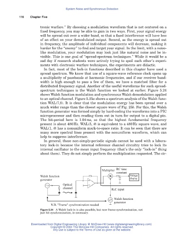
spectrum techniques is the Walsh function we looked at earlier. Figure 5.24
shows Walsh function modulation and synchronous Walsh demodulation applied
to an optical channel. Figure 5.25a shows a spectrum analysis of the Walsh func-
tion WAL(7,8). It is clear that the modulation energy has been spread over a
much wider range than the closest square wave of Fig. 25b. For this, the Walsh
function generator was formed simply by hard-coding the waveforms into a PIC
microprocessor and then reading them out in turn for output to a digital pin.
The bit-period here is 1.04ms, so that the highest fundamental frequency
present is about 480Hz. WAL(5, q) is equivalent to a 480Hz square wave, and
WAL(1, q) has a nonuniform mark-to-space ratio. It can be seen that there are
many more spectral lines present with the nonuniform waveform, which can
help to suppress interference.
In general, these non-simply-periodic signals cannot be used with a labora-
tory lock-in because the internal reference channel circuitry tries to lock its
internal oscillator to the mean input frequency (that’s the only “lock-in” thing
about them). They do not simply perform the multiplication requested. The cir-
Multiplier RC time
constant
Walsh function Voltage
display
generator -
Optical +
channel
Ref. input
Walsh function
generator
N.B. "Frame" synchronization needed
Figure 5.24 A Walsh lock-in is also possible, but now frame-synchronization, not
just bit-synchronization, is necessary.
Downloaded from Digital Engineering Library @ McGraw-Hill (www.digitalengineeringlibrary.com)
Copyright © 2004 The McGraw-Hill Companies. All rights reserved.
Any use is subject to the Terms of Use as given at the website.