
Page 69 - Photodetection and Measurement - Maximizing Performance in Optical Systems
P. 69
Fundamental Noise Basics and Calculations
62 Chapter Three
-20dB/decade: feedback
impedance dropping due to C f
Signal Gain (V /I ) Limit due to opamp
o p
log |A| (dB) f =1/2 R C open-loop gain
p
f f
1
f
p
1 + C /C (C /C ) GBW
p f
Noise Gain
p
f =1/2 R C
f p
2
+20dB/decade:
Detector impedance
dropping
f 10Hz log (Frequency)
2
(100M, 160pF) f 1kHz
1
(100M, 1.6pF)
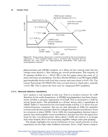
Figure 3.10 Noise peaking. Signal gain is limited primarily by the transimpedance
capacitance C f . The amplified voltage noise e n increases with frequency and can
dominate the noise power for high-capacitance photodiodes with high-value
transimpedance resistors.
photocurrents and 100MW resistors, it is often not the current noise but the
voltage noise density e n that defines our overall performance. The majority of
IC opamps exhibits an e n ª 20nV/ Hz in the flat region above the onset of 1/f
noise, but there are exceptions. The Burr-Brown OPA121 is an FET-input 2MHz
gain-bandwidth device with 5pA bias current and noise down to 6nV/ Hz . The
Linear Technology LT1792/93 offer bias currents down to 10pA and e n typically
4.5nV/ Hz . This is about the limit now for integrated FET amplifiers.
3.11.3 Nanowatt detection calculations
Let’s analyze a real example in this way. This is a sensitive receiver for 1nW
detection at low audio frequencies. A 100MW transimpedance has been chosen,
which exhibits a parasitic capacitance of 0.15pF. This is increased to 1.6pF by
2
circuit board strays. The photodiode is a 10mm device with a capacitance of
160pF. Table 3.7 summarizes the calculated results and Fig. 3.11 shows the cal-
culated frequency responses. You can see that although at 10Hz the amplifier
current noise density is greater than the voltage noise density contribution, there
is a crossover at about 100Hz. Up to 1kHz the transimpedance thermal noise is
greater than both amplifier noise contributions, but just less than the signal shot
noise for this 1nA photocurrent. Above about 1.5kHz the receiver is no longer
shot-noise limited, due to the increasing amplifier voltage noise gain peaking.
The design highlights the severe limitations of even small amounts of stray
capacitance on the high-value feedback resistance. Even 1.6pF causes a drop in
Downloaded from Digital Engineering Library @ McGraw-Hill (www.digitalengineeringlibrary.com)
Copyright © 2004 The McGraw-Hill Companies. All rights reserved.
Any use is subject to the Terms of Use as given at the website.