
Page 65 - Photodetection and Measurement - Maximizing Performance in Optical Systems
P. 65
Fundamental Noise Basics and Calculations
58 Chapter Three
2N3904 +12V
Variable Red AlGaAs 100k
supply 4.7k 1k LED 100nF
0–12V
BPX65 LMC7101
2x
100μF +
47nF - To scope,
10M 10M spectrum analyzer
100mm glass 99k
tube to couple LED 1.0k
to photodiode
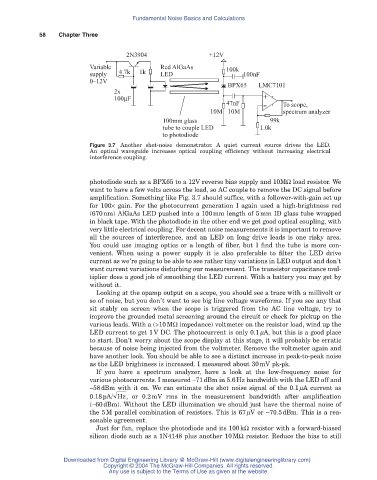
Figure 3.7 Another shot-noise demonstrator. A quiet current source drives the LED.
An optical waveguide increases optical coupling efficiency without increasing electrical
interference coupling.
photodiode such as a BPX65 to a 12V reverse bias supply and 10MW load resistor. We
want to have a few volts across the load, so AC couple to remove the DC signal before
amplification. Something like Fig. 3.7 should suffice, with a follower-with-gain set up
for 100¥ gain. For the photocurrent generation I again used a high-brightness red
(670nm) AlGaAs LED pushed into a 100mm length of 5mm ID glass tube wrapped
in black tape. With the photodiode in the other end we get good optical coupling, with
very little electrical coupling. For decent noise measurements it is important to remove
all the sources of interference, and an LED on long drive leads is one risky area.
You could use imaging optics or a length of fiber, but I find the tube is more con-
venient. When using a power supply it is also preferable to filter the LED drive
current as we’re going to be able to see rather tiny variations in LED output and don’t
want current variations disturbing our measurement. The transistor capacitance mul-
tiplier does a good job of smoothing the LED current. With a battery you may get by
without it.
Looking at the opamp output on a scope, you should see a trace with a millivolt or
so of noise, but you don’t want to see big line voltage waveforms. If you see any that
sit stably on screen when the scope is triggered from the AC line voltage, try to
improve the grounded metal screening around the circuit or check for pickup on the
various leads. With a (>10MW impedance) voltmeter on the resistor load, wind up the
LED current to get 1V DC. The photocurrent is only 0.1mA, but this is a good place
to start. Don’t worry about the scope display at this stage, it will probably be erratic
because of noise being injected from the voltmeter. Remove the voltmeter again and
have another look. You should be able to see a distinct increase in peak-to-peak noise
as the LED brightness is increased. I measured about 30mV pk-pk.
If you have a spectrum analyzer, have a look at the low-frequency noise for
various photocurrents. I measured -71dBm in 5.6Hz bandwidth with the LED off and
-58dBm with it on. We can estimate the shot noise signal of the 0.1mA current as
0.18pA/ Hz , or 0.2mV rms in the measurement bandwidth after amplification
(-60dBm). Without the LED illumination we should just have the thermal noise of
the 5M parallel combination of resistors. This is 67mV or -70.5dBm. This is a rea-
sonable agreement.
Just for fun, replace the photodiode and its 100kW resistor with a forward-biased
silicon diode such as a 1N4148 plus another 10MW resistor. Reduce the bias to still
Downloaded from Digital Engineering Library @ McGraw-Hill (www.digitalengineeringlibrary.com)
Copyright © 2004 The McGraw-Hill Companies. All rights reserved.
Any use is subject to the Terms of Use as given at the website.