
Page 62 - Photodetection and Measurement - Maximizing Performance in Optical Systems
P. 62
Fundamental Noise Basics and Calculations
Fundamental Noise Basics and Calculations 55
i n = 2 qI b = 2 qI e (3.13)
2
b
Ê
kT
e n = 4 kT r b + r e ˆ ¯ r e = qI e (3.14)
2
Ë
2
I b and I e are the transistor base and emitter currents, and r b, r e are the base
spreading resistance and emitter small-signal resistance. The transistor current
gain is represented by b.
For field effect devices the equivalent noise densities are:
kTC gs 2w 2
◊
i n = 2 qI g + 0 7 4 (3.15)
2
.
g m
kT
e n = 07 4 (3.16)
◊
2
.
g m
Here g m is the mutual conductance of the FET, I g is the gate leakage current,
and C gs is the input capacitance of the FET. The operating radian frequency is
w = 2pf.
3.9 Design Example: Free-Space Detection of an
LED—Big (Resistor) is Better
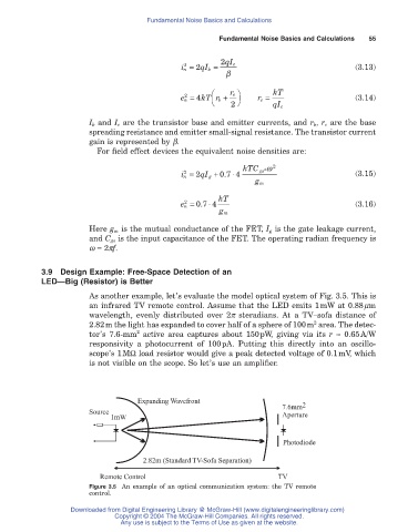
As another example, let’s evaluate the model optical system of Fig. 3.5. This is
an infrared TV remote control. Assume that the LED emits 1mW at 0.88mm
wavelength, evenly distributed over 2p steradians. At a TV–sofa distance of
2
2.82m the light has expanded to cover half of a sphere of 100m area. The detec-
2
tor’s 7.6-mm active area captures about 150pW, giving via its r ª 0.65A/W
responsivity a photocurrent of 100pA. Putting this directly into an oscillo-
scope’s 1MW load resistor would give a peak detected voltage of 0.1mV, which
is not visible on the scope. So let’s use an amplifier.
Expanding Wavefront
7.6mm 2
Source
1mW Aperture
Photodiode
2.82m (Standard TV-Sofa Separation)
Remote Control TV
Figure 3.5 An example of an optical communication system: the TV remote
control.
Downloaded from Digital Engineering Library @ McGraw-Hill (www.digitalengineeringlibrary.com)
Copyright © 2004 The McGraw-Hill Companies. All rights reserved.
Any use is subject to the Terms of Use as given at the website.