
Page 64 - Photodetection and Measurement - Maximizing Performance in Optical Systems
P. 64
Fundamental Noise Basics and Calculations
Fundamental Noise Basics and Calculations 57
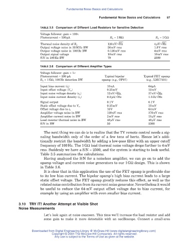
TABLE 3.5 Comparison of Different Load Resistors for Sensitive Detection
Voltage follower: gain = 100¥
Photocurrent = 100pA R L = 1MW R L = 1GW
126nV/ Hz 4mV/ Hz
Thermal noise density of R L
Output voltage noise in 20MHz BW 56mV rms 1.8V rms
Output voltage noise in 100Hz BW 0.126mV rms 4mV rms
Output signal voltage 10mV rms 10mV rms
S/N in 100Hz BW 79 2500
TABLE 3.6 Comparison of Different Amplifier Types
Voltage follower: gain = 1¥
Photocurrent = 100 pA Typical bipolar Typical FET opamp
R L = 1GW, 100Hz detection BW opamp (e.g., OP07) (e.g., LMC7101)
Input bias current (i b) 10nA 64pA
Input offset voltage (V os) 0.25mV 10mV
Input noise voltage density (e n ) 12nV/ Hz 37nV/ Hz
Input noise current density (i n ) 0.2pA/ Hz 1.5fA/ Hz
Signal output 0.1V 0.1V
0.25mV 10mV
Static offset voltage due to V os
10V 64mV
Offset voltage due to i b
Amplifier voltage noise in BW 120nV rms 370nV rms
Amplifier current noise in BW 2mV rms 15mV rms
Load resistor thermal noise in BW 40mV rms 40mV rms
S/N in BW 50 2300
The next thing we can do is to realize that the TV remote control needs a sig-
naling bandwidth only of the order of a few tens of hertz. Hence let’s addi-
tionally restrict the bandwidth by adding a low-pass filter with an upper cutoff
frequency of 100Hz. The 1GW load thermal noise voltage drops further to 4mV
rms. Suddenly we have a S/N ª 2500, and the system is starting to look useful.
Table 3.5 summarizes the calculations.
Having analyzed the S/N for a noiseless amplifier, we can go on to add the
opamp voltage and current noise generators to our 1GW design. This is shown
in Table 3.6.
It is clear that in this application the use of the FET opamp is preferable due
to its low bias current. The bipolar opamp’s high bias current leads to a large
static offset voltage. The FET opamp greatly reduces this effect, as well as the
related noise contribution from its current noise generator. Nevertheless it would
be useful to reduce the 64-mV output offset voltage due to bias current, for
example by using an amplifier with even smaller bias current.
3.10 TRY IT! Another Attempt at Visible Shot
Noise Measurements
Let’s look again at noise onscreen. This time we’ll increase the load resistor and add
some gain to make it more detectable with an oscilloscope. Connect a small-area
Downloaded from Digital Engineering Library @ McGraw-Hill (www.digitalengineeringlibrary.com)
Copyright © 2004 The McGraw-Hill Companies. All rights reserved.
Any use is subject to the Terms of Use as given at the website.