
Page 70 - Photodetection and Measurement - Maximizing Performance in Optical Systems
P. 70
Fundamental Noise Basics and Calculations
Fundamental Noise Basics and Calculations 63
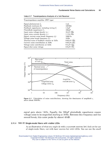
TABLE 3.7 Transimpedance Analysis of a 1nA Receiver
Transimpedance amplifier (FET type)
1nA
Signal photocurrent I p
100MW
Feedback resistance R f
1.6pF
Feedback capacitance, including wiring C f
160pF
Photodiode capacitance C p
Input noise voltage density (e n ) 10nV/ Hz
Input noise current density (i n) 1.1fA/ Hz
Signal, current noise break frequency (f 1 ) 1000Hz
Voltage noise break frequency (f 2) 10Hz
Thermal noise of feedback resistor at 1kHz 0.63mV/ Hz
Current noise contribution at 1kHz 0.05mV/ Hz
Voltage noise contribution at 1kHz 0.5mV/ Hz
Signal shot noise voltage 0.9mV/ Hz
10 -5
Shot noise
of 1nA I p Total noise
Output Voltage (V) 10 -7 Thermal noise
-6
of transimpedance
10
Amplifier
10 -8 Amplified amp. current noise i n
voltage noise e n
10 -9
3 4 5
1 10 100 10 10 10
Frequency (Hz)
Figure 3.11 Calculation of noise contributions, showing the dominance of amplified e n
above about 1500Hz.
signal gain above 1kHz. Equally, the 160pF photodiode capacitance causes
voltage noise to be magnified starting at 10Hz. Between this frequency and the
second break, this noise peaks by almost 40dB.
3.11.4 TRY IT! Single-mode fibers with visible LEDs
As an illustration of what you might do with a nanowatt receiver, let’s look at the use
of single-mode fibers, not with laser sources but with LEDs. You can use the small
Downloaded from Digital Engineering Library @ McGraw-Hill (www.digitalengineeringlibrary.com)
Copyright © 2004 The McGraw-Hill Companies. All rights reserved.
Any use is subject to the Terms of Use as given at the website.