
Page 75 - Photodetection and Measurement - Maximizing Performance in Optical Systems
P. 75
Fundamental Noise Basics and Calculations
68 Chapter Three
and make quantitative measurements over a wide dynamic range, as long as
the signals are quasistatic. Unfortunately, the fabulous performance of a good
spectrum analyzer does not come cheap, so they are found in labs only about 1
percent as often as a scope. As discussed in App. II, software-based frequency
analysis will suffice, but requires great care.
3.12.4 Narrow band filters
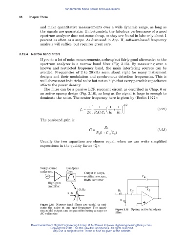
If you do a lot of noise measurements, a cheap but fairly good alternative to the
spectrum analyzer is a narrow band filter (Fig. 3.15). By measuring over a
known and restricted frequency band, the main interfering sources can be
avoided. Frequencies of 2 to 20kHz seem about right for many instrument
designs and their modulation and synchronous detection frequencies. This is
well above most industrial noise but not so high that every parasitic capacitance
affects the power density.
The filter can be a passive LCR resonant circuit as described in Chap. 6 or
an active opamp design (Fig. 3.16), as long as the signal is large to enough to
dominate the noise. The center frequency here is given by (Berlin 1977):
12
f o = 1 È 1 Ê 1 + 1 ˆ ˘ (3.22)
2p Í Î RC C 4 Ë R 1 R 3 ¯ ˙ ˚
5
2
The passband gain is:
G = R 5 (3.23)
R (1 + C C )
1
4
2
Usually the two capacitors are chosen equal, when we can write simplified
expressions in the quality factor (Q):
Noisy source Bandpass
under test filter
Output to scope,
rectifier/averager, C 4
RMS converter
High-gain
amplifier
10kHz R C R 5
1kHz 1 2
R 3
Figure 3.15 Narrow-band filters are useful to esti-
mate the noise at one spot-frequency. The quasi-
sinusoidal output can be quantified using a scope or Figure 3.16 Opamp active bandpass
AC voltmeter. filter.
Downloaded from Digital Engineering Library @ McGraw-Hill (www.digitalengineeringlibrary.com)
Copyright © 2004 The McGraw-Hill Companies. All rights reserved.
Any use is subject to the Terms of Use as given at the website.