
Page 79 - Photodetection and Measurement - Maximizing Performance in Optical Systems
P. 79
Fundamental Noise Basics and Calculations
72 Chapter Three
350
300
250
Voltage (mV) 200
150
100
50
0
-50 -40 -30 -20 -10 0 10 20 30 40 50
Time (ms)
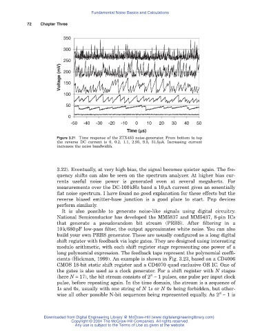
Figure 3.21 Time response of the ZTX453 noise-generator. From bottom to top
the reverse DC current is 0, 0.2, 1.1, 2.95, 9.5, 31.5mA. Increasing current
increases the noise bandwidth.
3.22). Eventually, at very high bias, the signal becomes quieter again. The fre-
quency shifts can also be seen on the spectrum analyzer. At higher bias cur-
rents useful noise power is generated even at several megahertz. For
measurements over the DC-100kHz band a 10mA current gives an essentially
flat noise spectrum. I have found no good explanation for these effects but the
reverse biased emitter-base junction is a good place to start. Pnp devices
perform similarly.
It is also possible to generate noise-like signals using digital circuitry.
National Semiconductor has developed the MM5837 and MM5437, 8-pin ICs
that generate a pseudorandom bit stream (PRBS). After filtering in a
10k/680pF low-pass filter, the output approximates white noise. You can also
build your own PRBS generator. These are usually configured as a long digital
shift register with feedback via logic gates. They are designed using interesting
modulo arithmetic, with each shift register stage representing one power of a
long polynomial expression. The feedback taps represent the polynomial coeffi-
cients (Hickman, 1999). An example is shown in Fig. 3.23, based on a CD4006
CMOS 18-bit static shift register and a CD4070 quad exclusive OR IC. One of
the gates is also used as a clock generator. For a shift register with N stages
N
(here N = 17), the bit stream consists of 2 - 1 pulses, one pulse per input clock
pulse, before repeating again. In the time domain, the stream is a sequence of
1s and 0s, usually with one string of N 1s or N 0s being forbidden, but other-
N
wise all other possible N-bit sequences being represented equally. As 2 - 1 is
Downloaded from Digital Engineering Library @ McGraw-Hill (www.digitalengineeringlibrary.com)
Copyright © 2004 The McGraw-Hill Companies. All rights reserved.
Any use is subject to the Terms of Use as given at the website.