
Page 304 - Plastics Engineering
P. 304
Processing of Plastics 287
is required if the moulding is separated cleanly from the runner. So for the
initial trials on a mould the gates are made as small as possible and are only
opened up if there are mould filling problems.
In a multi-cavity mould it is not always possible to arrange for the runner
length to each cavity to be the same. This means that cavities close to the
sprue would be filled quickly whereas cavities remote from the sprue receive
the melt later and at a reduced pressure. To alleviate this problem it is common
to use small gates close to the sprue and progressively increase the dimensions
of the gates further along the runners. This has the effect of balancing the fill
of the cavities. If a single cavity mould is multi-gated then here again it may
be beneficial to balance the flow by using various gate sizes.
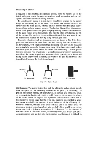
Examples of gates which are in common use are shown in Fig. 4.36. Sprue
gates are used when the sprue bush can feed directly into the mould cavity
as, for example, with single symmetrical moulding such as buckets. Pin gates
are particularly successful because they cause high shear rates which reduce
the viscosity of the plastic and so the mould fills more easily. The side gate is
the most common type of gate and is a simple rectangular section feeding into
the side of the cavity. A particular attraction of this type of gate is that mould
filling can be improved by increasing the width of the gate but the freeze time
is unaffected because the depth is unchanged.
(a1 Sprue gate (bl Pin gate (c) Side gate
Fig. 4.36 Types of gate
(b) Runners: The runner is the flow path by which the molten plastic travels
from the sprue (i.e. the moulding machine) to the gates (i.e. the cavity). To
prevent the runner freezing off prematurely, its surface area should be small
so as to minimise heat transfer to the mould. However, the cross sectional area
of the runner should be large so that it presents little resistance to the flow of
the plastic but not so large that the cycle time needs to be extended to allow
the runner to solidify for ejection. A good indication of the efficiency of a
runner is, therefore, the ratio of its cross-sectional area to its surface area. For
example, a semi-circular channel cut into one half of the mould is convenient
to machine but it only has an area ratio of 0.153 D where D is the diameter of
the semi-circle. A full round runner, on the other hand, has a ratio of 0.25 D.
A square section also has this ratio but is seldom used because it is difficult to