
Page 299 - Plastics Engineering
P. 299
282 Processing of Plastics
to inject melt into the mould. A typical injection moulding machine cycle is
illustrated in Fig. 4.31. It involves the following stages:
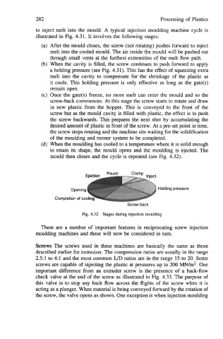
(a) After the mould closes, the screw (not rotating) pushes forward to inject
melt into the cooled mould. The air inside the mould will be pushed out
through small vents at the furthest extremities of the melt flow path.
(b) When the cavity is filled, the screw continues to push forward to apply
a holding pressure (see Fig. 4.31). This has the effect of squeezing extra
melt into the cavity to compensate for the shrinkage of the plastic as
it cools. This holding pressure is only effective as long as the gate@)
remain open.
(c) Once the gate@) freeze, no more melt can enter the mould and so the
screw-back commences. At this stage the screw starts to rotate and draw
in new plastic from the hopper. This is conveyed to the front of the
screw but as the mould cavity is filled with plastic, the effect is to push
the screw backwards. This prepares the next shot by accumulating the
desired amount of plastic in front of the screw. At a pre-set point in time,
the screw stops rotating and the machine sits waiting for the solidification
of the moulding and runner system to be completed.
(d) When the moulding has cooled to a temperature where it is solid enough
to retain its shape, the mould opens and the moulding is ejected. The
mould then closes and the cycle is repeated (see Fig. 4.32).
Holding pressure
Screw back
Fig. 4.32 Stages during injection moulding
There are a number of important features in reciprocating screw injection
moulding machines and these will now be considered in turn.
Screws The screws used in these machines are basically the same as those
described earlier for extrusion. The compression ratios are usually in the range
251 to 4:l and the most common UD ratios are in the range 15 to 20. Some
screws are capable of injecting the plastic at pressures up to 200 MN/m*. One
important difference from an extruder screw is the presence of a back-flow
check valve at the end of the screw as illustrated in Fig. 4.33. The purpose of
this valve is to stop any back flow across the flights of the screw when it is
acting as a plunger. When material is being conveyed forward by the rotation of
the screw, the valve opens as shown. One exception is when injection moulding