
Page 135 - Power Electronic Control in Electrical Systems
P. 135
//SYS21/F:/PEC/REVISES_10-11-01/075065126-CH004.3D ± 123 ± [106±152/47] 17.11.2001 9:54AM
Power electronic control in electrical systems 123
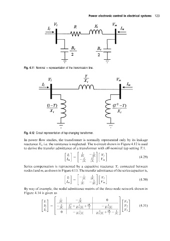
Fig. 4.11 Nominal representation of the transmission line.
Fig. 4.12 Circuit representation of tap-changing transformer.
In power flow studies, the transformer is normally represented only by its leakage
reactance X t , i.e. the resistance is neglected. The p-circuit shown in Figure 4.12 is used
to derive the transfer admittance of a transformer with off-nominal tap setting T:1.
" #
1 T
I l jX t jX t V l
T T 2 (4:29)
I m V m
jX t jX t
Series compensation is represented by a capacitive reactance X c connected between
nodes l and m, as shown in Figure 4.13. The transfer admittance of the series capacitor is,
" #
1 1
I l jX c jX c V l
1 1 (4:30)
I m V m
jX c jX c
By way of example, the nodal admittance matrix of the three-node network shown in
Figure 4.14 is given as
2 3
1 T
2 3 0 2 3
I 1 jX t jX t 7 V 1
6
6 T T 2 1 jB c 1 7 (4:31)
4 I 2 5 6 7 V 2 5
4
jX t jX t R jX l 2 R jX l
4 5
I 3 1 1 1 V 3
0 jB c
R jX l R jX l 2 jX c