
Page 134 - Power Electronic Control in Electrical Systems
P. 134
//SYS21/F:/PEC/REVISES_10-11-01/075065126-CH004.3D ± 122 ± [106±152/47] 17.11.2001 9:54AM
122 Power flows in compensation and control studies
of node the voltage magnitude and phase angle are known variables, whilst the
active and reactive powers are the unknown variables.
4.4.2 Conventional power plant representation
Alternating current power transmission networks are designed and operated in a
three-phase manner. However, for the purpose of conventional power flow studies, a
perfect geometric balance between all three phases of the power network is assumed
to exist. In most cases this is a reasonable assumption, and allows the analysis to be
carried out on a per-phase basis, using only the positive sequence parameters of the
power plant components. More realistic, though more time consuming solutions may
be achieved by means of three-phase power flow studies.
The plant components of the electrical power network normally represented in
power flow studies are generators, transformers, transmission lines, loads and passive
shunt and series compensation. Substation busbars are represented as buses, i.e.
nodal points in the power network. Nodal transfer admittance representations are
used for transmission lines and transformers whereas generators and loads are
represented by sources/sinks of active and reactive power.
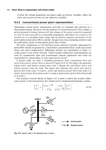
A generic node, say node l, including generation, load, transmission lines and
active and reactive power flows is shown in Figure 4.10. In this figure, the generator
injects active and reactive powers into node l whereas the load draws active and
reactive powers from the node. The figure also indicates that active and reactive
powers flow from node l to node k, active and reactive powers flow from node n to
node l, active power flows from node l to node m and reactive power flows from node
m to node l.
The nominal p-circuit shown in Figure 4.11 is used to derive the transfer admit-
tance matrix of the transmission line model used in fundamental frequency studies.
1 1
" #
jB c
I l 2 V l
R jX l R jX l
(4:28)
I m 1 1 jB c V m
R jX l R jX l 2
Fig. 4.10 Generic node of the electrical power network.