
Page 136 - Power Electronic Control in Electrical Systems
P. 136
//SYS21/F:/PEC/REVISES_10-11-01/075065126-CH004.3D ± 124 ± [106±152/47] 17.11.2001 9:54AM
124 Power flows in compensation and control studies
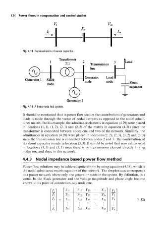
Fig. 4.13 Representation of series capacitor.
Fig. 4.14 A three-node test system.
It should be mentioned that in power flow studies the contribution of generators and
loads is made through the vector of nodal currents as opposed to the nodal admit-
tance matrix. In this example, the admittance elements in equation (4.29) were placed
in locations (1, 1), (1, 2), (2, 1) and (2, 2) of the matrix in equation (4.31) since the
transformer is connected between nodes one and two of the network. Similarly, the
admittances in equation (4.28) were placed in locations (2, 2), (2, 3), (3, 2) and (3, 3)
since the transmission line is connected between nodes 2 and 3. The contribution of
the shunt capacitor is only in location (3, 3). It should be noted that zero entries exist
in locations (1, 3) and (3, 1) since there is no transmission element directly linking
nodes one and three in this network.
4.4.3 Nodal impedance based power flow method
Power flow solutions may be achieved quite simply by using equation (4.18), which is
the nodal admittance matrix equation of the network. The simplest case corresponds
to a power network where only one generator exists in the system. By definition, this
would be the Slack generator and the voltage magnitude and phase angle become
known at its point of connection, say node one,
2 3
2 3 2 3
Y 11 Y 12 Y 13 Y 1n
I 1 V 1
6 7
I 2 6 Y 21 Y 22 Y 23 Y 2n 7 V 2
6 7 6 7
6 7 6 7
6 7
6 7 6 7
I 3 7 6 Y 31 Y 32 Y 33 (4:32)
. . . . .
6 Y 3n 7 V 3 7
6
6 7
6 . 7 . . . . 6 . 7
. . 5 6 . . . . . 7 . . 5
4 4
4 . 5
I n Y n1 Y n2 Y n3 Y nn V n