Page 131 - Power Electronic Control in Electrical Systems
P. 131

//SYS21/F:/PEC/REVISES_10-11-01/075065126-CH004.3D ± 119 ± [106±152/47] 17.11.2001 9:54AM


                                                            Power electronic control in electrical systems 119

                      3. If no direct connection exists between nodes i and j then the corresponding off-
                         diagonal element in the nodal admittance matrix will have a zero entry.
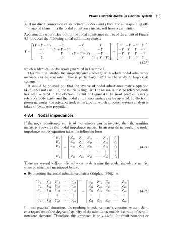
                      Applying this set of rules to form the nodal admittance matrix of the circuit of Figure
                      4.8 produces the following nodal admittance matrix
                           (Y ‡Y  Y)       Y          Y          Y           Y    Y  Y    Y
                          2                                             3  2                3
                                Y      (Y ‡Y  Y)      Y           Y          Y   Y    Y   Y
                          6                                             7  6                7
                      Y ˆ  6                                            7  ˆ  6             7
                                Y          Y      (Y ‡Y  Y)       Y          Y   Y    Y   Y
                          4                                             5  4                5
                                Y          Y          Y      (Y ‡Y  Y)       Y    Y  Y    Y
                                                                                         (4:23)
                      which is identical to the result generated in Example 1.
                        This result illustrates the simplicity and efficiency with which nodal admittance
                      matrices can be generated. This is particularly useful in the study of large-scale
                      systems.
                        It should be pointed out that the inverse of nodal admittance matrix equation
                      (4.23) does not exist, i.e. the matrix is singular. The reason is that no reference node
                      has been selected in the electrical circuit of Figure 4.8. In most practical cases a
                      reference node exists and the nodal admittance matrix can be inverted. In electrical
                      power networks, the reference node is the ground, which in power systems analysis is
                      taken to be at zero potential.

                      4.3.4   Nodal impedances

                      If the nodal admittance matrix of the network can be inverted then the resulting
                      matrix is known as the nodal impedance matrix. In an n-node network, the nodal
                      impedance matrix equation takes the following form
                                       2   3   2                       32   3
                                         V 1     Z 11  Z 12  Z 13      Z 1n  I 1
                                         V 2     Z 21  Z 22  Z 23      Z 2n  I 2
                                       6   7   6                       76   7
                                       6   7   6                       76   7
                                                 Z 31  Z 32  Z 33                        (4:24)
                                       6   7   6                       76   7
                                                  .    .    .   .
                                       6  V 3 7 ˆ 6                Z 3n 76  I 3 7
                                       6  . 7  6  .    .    .   .    . 76  . 7
                                         . . 5    .    .    .    .   . . 54  . . 5
                                       4       4
                                         V n     Z n1  Z n2  Z n3      Z nn  I n
                      There are several well-established ways to determine the nodal impedance matrix,
                      some of which are mentioned below:
                      . By inverting the nodal admittance matrix (Shipley, 1976), i.e.
                            2                       3  1  2                       3
                              Y 11  Y 12  Y 13      Y 1n   Z 11  Z 12  Z 13       Z 1n
                            6  Y 21  Y 22  Y 23      Y 2n  7  6  Z 21  Z 22  Z 23       Z 2n  7
                            6                       7     6                       7
                            6  Y 31  Y 32  Y 33     7     6  Z 31  Z 32  Z 33       7    (4:25)
                               .    .    .   .              .    .    .   .
                            6                    Y 3n 7 ˆ 6                   Z 3n 7
                            6  .    .    .    .   . 7     6  .   .    .    .   . 7
                            4  .    .    .    .   . . 5   4  .   .    .     .  . . 5
                              Y n1  Y n2  Y n3      Y nn   Z n1  Z n2  Z n3       Z nn
                      In most practical situations, the resulting impedance matrix contains no zero elem-
                      ents regardless of the degree of sparsity of the admittance matrix, i.e. ratio of zero to
                      non-zero elements. Therefore, this approach is only useful for small networks or
   126   127   128   129   130   131   132   133   134   135   136