
Page 289 - Power Electronic Control in Electrical Systems
P. 289
//SYS21/F:/PEC/REVISES_10-11-01/075065126-CH007.3D ± 277 ± [263±289/27] 17.11.2001 10:25AM
Power electronic control in electrical systems 277
connected TCR does not prevent completely the third harmonic currents and their
multiples from reaching the network. It should be remarked that under balanced
operation, these harmonic currents should be confined within the delta connected
circuit. Also, as expected, TCR currents above the 13th harmonic term are quite
small and may be ignored in most network harmonic studies.
Sometimes it is useful to use simplified expressions to check the sanity of the
results. In this case, we shall calculate the fundamental frequency, positive sequence
component of the TCR current by using the following equation (Miller, 1982)
(s sin s) V
I 1 A rms (7:37)
p X L
which gives the following result
p ) sin 120 3
(120 180 33 10
I 1 p 263:48 A rms (7:38)
p(2p 50 0:09) 3
This value agrees rather well with the positive sequence value derived from apply-
ing symmetrical components to the fundamental frequency three-phase currents
given in Table 7.1, i.e. 263.47 A rms.
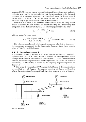
7.4.3.2 Numerical example 3
A portion of a 220-kVpower system for which complete information exists in the
open literature (Acha et al., 1989) is used to illustrate the results produced by the
three-phase TCR model. The system is shown in Figure 7.7. This is a well-studied test
network, which shows a parallel resonance laying between the 4th and 5th harmonic
frequencies, i.e. 200±250 Hz, as shown by the frequency response impedance in
Figure 7.8.
A delta connected three-phase TCR is connected at busbar 1. Transmission lines
are modelled with full frequency-dependence, geometric imbalances and long-line
effects. Generators, transformers and loads have been assumed to behave linearly.
Fig. 7.7 Test system.