
Page 291 - Power Electronic Control in Electrical Systems
P. 291
//SYS21/F:/PEC/REVISES_10-11-01/075065126-CH007.3D ± 279 ± [263±289/27] 17.11.2001 10:25AM
Power electronic control in electrical systems 279
12
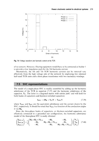
Phase a
Phase b
10
Phase c
8
[%]
Voltage 6
4
2
0
2 4 6 8 10 12 14 16
Order of harmonic
(b)
Fig. 7.9 Voltage waveform and harmonic content at the TCR.
of no concern. However, filtering equipment would have to be connected at busbar 1
to provide a low impedance path for the 5th harmonic current.
Alternatively, the 5th and 7th TCR harmonic currents can be removed very
effectively from the high voltage side of the network by employing two identical
half-sized TCR units and a three phase transformer with two secondary windings.
7.5 SVC representations
The model of a single-phase SVC is readily assembled by adding up the harmonic
admittance of the TCR in equation (7.27) and the harmonic admittance of the
capacitor, Y C . The latter is a diagonal matrix with entries johC and will hold for
both banks of capacitors and thyristor-switched capacitors
I SVC (H R Y C )V Y SVC V (7:39)
where Y SVC and I SVC are the equivalent admittance and the current drawn by the
SVC, respectively. It should be noted that Y SVC is a function of the conduction angles
s via H R .
Since the three-phase banks of capacitors, or thyristor-switched capacitors, are
effectively connected in a grounded star configuration, the harmonic admittance
model of the three-phase SVC is easily obtained
0 1 0 10 1
I SVC,A H 1 H 2 3Y C,1 H 2 H 1 V A
1
@ I SVC,B A @ H 2 H 2 H 3 3Y C,2 H 3 A@ V B A (7:40)
3
I SVC,C H 1 H 3 H 3 H 1 3Y C,3 V C