
Page 292 - Power Electronic Control in Electrical Systems
P. 292
//SYS21/F:/PEC/REVISES_10-11-01/075065126-CH007.3D ± 280 ± [263±289/27] 17.11.2001 10:25AM
280 Harmonic studies of power compensating plant
7.6 Thyristor-controlled series compensation
The TCSC steady-state response may be calculated by solving the TCSC differential
equations using a suitable numeric integration method or by expressing the TCSC
equations in algebraic form and then using a phasorial method. The former approach
involves the integration of the differential equations over many cycles until the
transient response dies out. This solution method is rich in information since the
full evolution of the response is captured, from transient inception to steady-state
operation, but problems may arise when solving lightly damped circuits because of
the low attenuation of the transient response. Two different solution flavours emerge
from the phasor approach: (i) A non-linear equivalent impedance expression is
derived for the TCSC and solved by iteration. The solution method is accurate and
converges very robustly towards the convergence, but it only yields information
about the fundamental frequency, steady-state solution; and (ii) Alternatively, the
TCSC steady-state operation may be determined by using fundamental and har-
monic frequency phasors leading to non-iterative solutions in the presence of low to
moderate harmonic voltage distortion. The solution takes place in the harmonic
domain and this is the approach presented in Section 7.6.2. The method yields full
information for the fundamental and harmonic frequency TCSC parameters but no
transient information is available.
7.6.1 Main parameters and operating modes
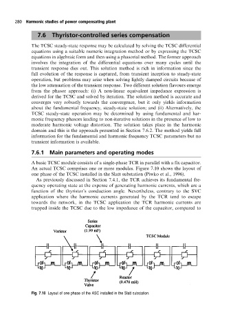
A basic TCSC module consists of a single-phase TCR in parallel with a fix capacitor.
An actual TCSC comprises one or more modules. Figure 7.10 shows the layout of
one phase of the TCSC installed in the Slatt substation (Piwko et al., 1996).
As previously discussed in Section 7.4.1, the TCR achieves its fundamental fre-
quency operating state at the expense of generating harmonic currents, which are a
function of the thyristor's conduction angle. Nevertheless, contrary to the SVC
application where the harmonic currents generated by the TCR tend to escape
towards the network, in the TCSC application the TCR harmonic currents are
trapped inside the TCSC due to the low impedance of the capacitor, compared to
Fig. 7.10 Layout of one phase of the ASC installed in the Slatt substation.