
Page 297 - Power Electronic Control in Electrical Systems
P. 297
//SYS21/F:/PEC/REVISES_10-11-01/075065126-CH007.3D ± 285 ± [263±289/27] 17.11.2001 10:25AM
Power electronic control in electrical systems 285
addition to the fundamental frequency component. Figure 7.15(a) corresponds to
the accurate solution whereas the result in Figure 7.15(b) was obtained by using
only the fundamental frequency component, i.e. the harmonic terms were neglected.
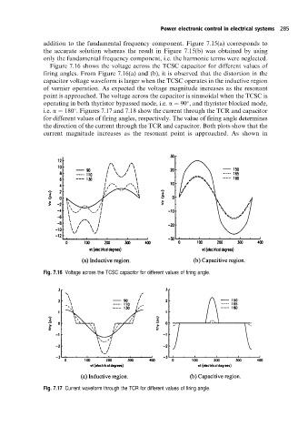
Figure 7.16 shows the voltage across the TCSC capacitor for different values of
firing angles. From Figure 7.16(a) and (b), it is observed that the distortion in the
capacitor voltage waveform is larger when the TCSC operates in the inductive region
of vernier operation. As expected the voltage magnitude increases as the resonant
point is approached. The voltage across the capacitor is sinusoidal when the TCSC is
operating in both thyristor bypassed mode, i.e. a 90 , and thyristor blocked mode,
i.e. a 180 . Figures 7.17 and 7.18 show the current through the TCR and capacitor
for different values of firing angles, respectively. The value of firing angle determines
the direction of the current through the TCR and capacitor. Both plots show that the
current magnitude increases as the resonant point is approached. As shown in
Fig. 7.16 Voltage across the TCSC capacitor for different values of firing angle.
Fig. 7.17 Current waveform through the TCR for different values of firing angle.