
Page 298 - Power Electronic Control in Electrical Systems
P. 298
//SYS21/F:/PEC/REVISES_10-11-01/075065126-CH007.3D ± 286 ± [263±289/27] 17.11.2001 10:25AM
286 Harmonic studies of power compensating plant
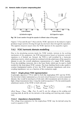
Fig. 7.18 Current waveform through the capacitor for different values of firing angle.
Figures 7.17(a) and (b) and 7.18(a) and (b), TCSC operation in the inductive region
produces larger currents flowing through the thyristors than through the capacitors.
The opposite situation occurs when the TCSC operates in the capacitive region.
7.6.2 TCSC harmonic domain modelling
Due to the circulating currents inside the TCSC module, intrinsic in the working
mechanism of this equipment, the TCR representation based on harmonic currents
injections is of limited use. Instead, the TCR is well modelled by a harmonic
admittance matrix, which can then be combined with the admittance of the capacitive
element to give the overall admittance representation of a single TCSC module.
From the modelling viewpoint, this is the basic block, which may be used to build
models for the three-phase TCSC systems. The basic building block is also useful to
conduct fundamental studies of how the TCSC harmonic impedances and cross-
coupling impedances vary as a function of the conduction angle.
7.6.2.1 Single-phase TCSC representation
In principle, equation (7.39) is valid for both the single-phase SVC and the TCSC,
but the latter is better represented as a two-port circuit because it is a series connected
element, that would be interfaced at both ends with transmission network plant, i.e.
high-voltage transmission lines. Using the result in equation (7.39), the nodal transfer
admittance matrix of the TCSC is built with ease
I s Y TCSC Y TCSC V s
(7:46)
I r Y TCSC Y TCSC V r
where Y TCSC Y SVC (H R Y C ), V s and V r are the voltages at the sending and
receiving ends, I s and I r are the currents at the sending and receiving ends, respect-
ively.
7.6.2.2 Impedance characteristics
The voltage drop expression for the single-phase TCSC may be derived using the
result in equation (7.39)