
Page 295 - Power Electronic Control in Electrical Systems
P. 295
//SYS21/F:/PEC/REVISES_10-11-01/075065126-CH007.3D ± 283 ± [263±289/27] 17.11.2001 10:25AM
Power electronic control in electrical systems 283
80000 6000
60000
4000
Voltage
40000
2000
20000 V
A O
M L
P 0 0 T
S 0.0 2.0 4.0 6.0 8.0 10.0 12.0 14.0 16.0 S
–20000
–2000
–40000
Current –4000
–60000
–80000 –6000
TIME (mS)
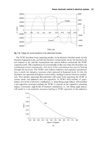
Fig. 7.13 Voltage and current waveforms in the bidirectional thyristors.
The TCSC has three basic operating modes: (i) the thyristor blocked mode; (ii) the
thyristor bypassed mode; and (iii) the thyristor vernier mode. In (i), the thyristors do
not conduct at all, and the transmission line current follows exclusively the TCSC
capacitive path. The condition in (ii) corresponds to the case when the thyristors are
conducting current continuously, with most of the transmission line current flowing
through the thyristors. The TCSCs with realistic inductive and capacitive parameters
have a small, net inductive reactance when operated in bypassed mode. In (iii), the
thyristors are operated with phase control delay, leading to partial thyristor conduc-
tion. Two distinct operating characteristics will result from operating the TCSC in
vernier mode, one inductive and one capacitive. In TCSCs with realistic LC para-
meters, low levels of thyristor conduction, i.e. large firing angle delays, will establish
a net capacitive reactance making the TCSC to operate in the capacitive operating
region. Conversely, high levels of thyristor conduction, i.e. low firing angle delays,
will result in a net inductive reactance leading to TCSC operation in the inductive
0.12
0.1
0.08
3rd
V3/V1 0.06
0.04
0.02
0
125 130 135 140 145 150 155 160 165 170 175 180
Alpha in Degrees
(a)