
Page 296 - Power Electronic Control in Electrical Systems
P. 296
//SYS21/F:/PEC/REVISES_10-11-01/075065126-CH007.3D ± 284 ± [263±289/27] 17.11.2001 10:25AM
284 Harmonic studies of power compensating plant
0.005
9th 7th
0
125 130 135 140 145 150 155 160 165 170 175 180
–0.005
Vn/V1
–0.01 5th
–0.015
–0.02
Alpha in Degrees
(b)
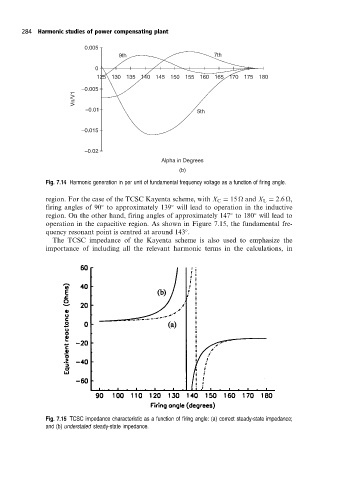
Fig. 7.14 Harmonic generation in per unit of fundamental frequency voltage as a function of firing angle.
region. For the case of the TCSC Kayenta scheme, with X C 15
and X L 2:6
,
firing angles of 90 to approximately 139 will lead to operation in the inductive
region. On the other hand, firing angles of approximately 147 to 180 will lead to
operation in the capacitive region. As shown in Figure 7.15, the fundamental fre-
quency resonant point is centred at around 143 .
The TCSC impedance of the Kayenta scheme is also used to emphasize the
importance of including all the relevant harmonic terms in the calculations, in
Fig. 7.15 TCSC impedance characteristic as a function of firing angle: (a) correct steady-state impedance;
and (b) understated steady-state impedance.