
Page 75 - Power Electronic Control in Electrical Systems
P. 75
//SYS21/F:/PEC/REVISES_10-11-01/075065126-CH002.3D ± 64 ± [31±81/51] 17.11.2001 9:49AM
64 Power systems engineering ± fundamental concepts
where the hi symbols mean `time average' over one cycle, f is the phase angle
1
between V ac and I a ,and f is the phase angle between V bc and I b . These relationships
2
are further illustrated in Figure 2.36, and under balanced conditions
P 1 V LL I L cos (30 f)
(2:41)
P 2 V LL I L cos (30 f)
from which it follows that
p P 1 P 2
tan f 3 (2:42)
P 1 P 2
The wattmeter readings can be used in this equation to determine the power
factor.
2.11 Polyphase transformers
2.11.1 Definition
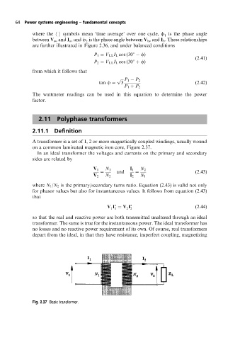
A transformer is a set of 1, 2 or more magnetically coupled windings, usually wound
on a common laminated magnetic iron core, Figure 2.37.
In an ideal transformer the voltages and currents on the primary and secondary
sides are related by
V 1 N 1 I 1 N 2
and (2:43)
V 2 N 2 I 2 N 1
where N 1 /N 2 is the primary/secondary turns ratio. Equation (2.43) is valid not only
for phasor values but also for instantaneous values. It follows from equation (2.43)
that
V I V I (2:44)
1 1 2 2
so that the real and reactive power are both transmitted unaltered through an ideal
transformer. The same is true for the instantaneous power. The ideal transformer has
no losses and no reactive power requirement of its own. Of course, real transformers
depart from the ideal, in that they have resistance, imperfect coupling, magnetizing
Fig. 2.37 Basic transformer.