
Page 77 - Power Electronic Control in Electrical Systems
P. 77
//SYS21/F:/PEC/REVISES_10-11-01/075065126-CH002.3D ± 66 ± [31±81/51] 17.11.2001 9:49AM
66 Power systems engineering ± fundamental concepts
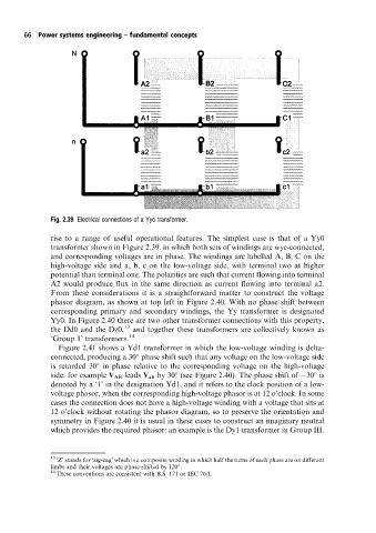
Fig. 2.39 Electrical connections of a Yyo transformer.
rise to a range of useful operational features. The simplest case is that of a Yy0
transformer shown in Figure 2.39. in which both sets of windings are wye-connected,
and corresponding voltages are in phase. The windings are labelled A, B, C on the
high-voltage side and a, b, c on the low-voltage side, with terminal two at higher
potential than terminal one. The polarities are such that current flowing into terminal
A2 would produce flux in the same direction as current flowing into terminal a2.
From these considerations it is a straightforward matter to construct the voltage
phasor diagram, as shown at top left in Figure 2.40. With no phase shift between
corresponding primary and secondary windings, the Yy transformer is designated
Yy0. In Figure 2.40 there are two other transformer connections with this property,
the Dd0 and the Dz0, 13 and together these transformers are collectively known as
`Group 1' transformers. 14
Figure 2.41 shows a Yd1 transformer in which the low-voltage winding is delta-
connected, producing a 30 phase shift such that any voltage on the low-voltage side
is retarded 30 in phase relative to the corresponding voltage on the high-voltage
side: for example V AB leads V ab by 30 (see Figure 2.40). The phase shift of 30 is
denoted by a `1' in the designation Yd1, and it refers to the clockposition of a low-
voltage phasor, when the corresponding high-voltage phasor is at 12 o'clock. In some
cases the connection does not have a high-voltage winding with a voltage that sits at
12 o'clockwithout rotating the phasor diagram, so to preserve the orientation and
symmetry in Figure 2.40 it is usual in these cases to construct an imaginary neutral
which provides the required phasor: an example is the Dy1 transformer in Group III.
13
`Z' stands for `zig-zag' which is a composite winding in which half the turns of each phase are on different
limbs and their voltages are phase-shifted by 120 .
14
These conventions are consistent with B.S. 171 or IEC 76/I.