
Page 78 - Power Electronic Control in Electrical Systems
P. 78
//SYS21/F:/PEC/REVISES_10-11-01/075065126-CH002.3D ± 67 ± [31±81/51] 17.11.2001 9:49AM
Power electronic control in electrical systems 67
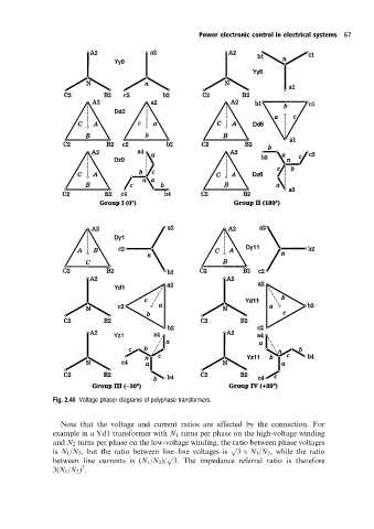
Fig. 2.40 Voltage phasor diagrams of polyphase transformers.
Note that the voltage and current ratios are affected by the connection. For
example in a Yd1 transformer with N 1 turns per phase on the high-voltage winding
and N 2 turns per phase on the low-voltage winding, the ratio between phase voltages
p
is N 1 /N 2 , but the ratio between line±line voltages is 3 N 1 /N 2 , while the ratio
p
between line currents is (N 1 /N 2 )/ 3. The impedance referral ratio is therefore
2
3(N 1 /N 2 ) .