
Page 76 - Power Electronic Control in Electrical Systems
P. 76
//SYS21/F:/PEC/REVISES_10-11-01/075065126-CH002.3D ± 65 ± [31±81/51] 17.11.2001 9:49AM
Power electronic control in electrical systems 65
current, and core losses; but these can be neglected when considering many of the
main functions of transformers. 12
The impedance `looking into' the transformer at the primary terminals is the ratio
2
V 1 /I 1 , and from equation (2.43) this is equal to (N 1 /N 2 ) Z L , where Z L is the load
impedance connected on the secondary side. This is called the `referred' impedance,
0
Z . If the primary side has a higher voltage than the secondary side, i.e. N 1 /N 2 > 1,
L
0
then Z will be larger than Z L . For example, in an 11 kV/415 V transformer the
L
2
impedance ratio is (11 000/415) 702:5.
2.11.2 Functions
Transformers have several functions in power transmission and distribution, for
example:
(a) transform voltage level for optimum transmission
(b) isolate coupled circuits
(c) impedance matching
(d) introduce series impedance (to limit fault current)
(e) create a neutral point (e.g. ground connection remote from power station)
(f ) suppress harmonics (especially triplen harmonics)
(g) provide tappings for loads along a tranmission line
(h) produce phase shift or multiple phases (e.g. for multiple-pulse converters)
(i) frequency-multiplication (saturated core)
(j) constant-voltage reactive compensation (saturated core).
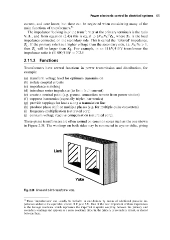
Three-phase transformers are often wound on common cores such as the one shown
in Figure 2.38. The windings on both sides may be connected in wye or delta, giving
Fig. 2.38 Unwound 3-limb transformer core.
12
These `imperfections' can usually be included in calculations by means of additional parasitic im-
pedances added to the equivalent circuit of Figure 2.37. One of the most important of these impedances
is the leakage reactance which represents the imperfect magnetic coupling between the primary and
secondary windings and appears as a series reactance either in the primary or secondary circuit, or shared
between them.