
Page 79 - Power Electronic Control in Electrical Systems
P. 79
//SYS21/F:/PEC/REVISES_10-11-01/075065126-CH002.3D ± 68 ± [31±81/51] 17.11.2001 9:49AM
68 Power systems engineering ± fundamental concepts
Fig. 2.41 Yd1 transformer.
2.11.3 Parallel operation
For connection in parallel, transformers must be designed for the same frequency
and the same primary and secondary voltages, and they must be connected with the
correct polarities. (That's why the labelling of transformer terminals is so important.)
The way in which parallel transformers share the load is important. To introduce
the analysis it might be helpful to consider the simpler case of two DC batteries
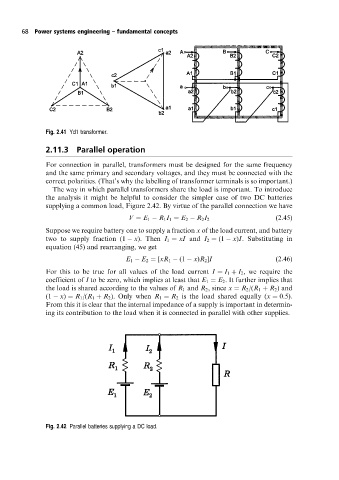
supplying a common load, Figure 2.42. By virtue of the parallel connection we have
V E 1 R 1 I 1 E 2 R 2 I 2 (2:45)
Suppose we require battery one to supply a fraction x of the load current, and battery
two to supply fraction (1 x). Then I 1 xI and I 2 (1 x)I. Substituting in
equation (45) and rearranging, we get
E 1 E 2 [xR 1 (1 x)R 2 ]I (2:46)
For this to be true for all values of the load current I I 1 I 2 , we require the
coefficient of I to be zero, which implies at least that E 1 E 2 . It further implies that
the load is shared according to the values of R 1 and R 2 , since x R 2 /(R 1 R 2 ) and
(1 x) R 1 /(R 1 R 2 ). Only when R 1 R 2 is the load shared equally (x 0:5).
From this it is clear that the internal impedance of a supply is important in determin-
ing its contribution to the load when it is connected in parallel with other supplies.
Fig. 2.42 Parallel batteries supplying a DC load.