Page 80 - Power Electronic Control in Electrical Systems
P. 80

//SYS21/F:/PEC/REVISES_10-11-01/075065126-CH002.3D ± 69 ± [31±81/51] 17.11.2001 9:49AM


                                                             Power electronic control in electrical systems 69


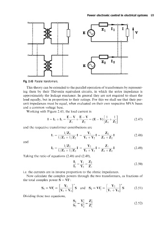
                      Fig. 2.43 Parallel transformers.

                        This theory can be extended to the parallel operation of transformers by represent-
                      ing them by their The  venin equivalent circuits, in which the series impedance is
                      approximately the leakage reactance. In general they are not required to share the
                      load equally, but in proportion to their ratings. For this we shall see that their per-
                      unit impedances must be equal, when evaluated on their own respective MVA bases
                      and a common voltage base.
                        Working with Figure 2.43, the load current is
                                                E   V   E   V            1   1
                                     I ˆ I 1 ‡ I 2 ˆ  ‡       ˆ (E   V)   ‡              (2:47)
                                                  Z 1    Z 2           Z 1  Z 2
                      and the respective transformer contributions are
                                              1=Z 1          Y 1       Z 2
                                       I 1 ˆ          I ˆ         I ˆ       I            (2:48)
                                           1=Z 1 ‡ 1=Z 2  Y 1 ‡ Y 2  Z 1 ‡ Z 2
                      and
                                              1=Z 2          Y 2       Z 1
                                       I 2 ˆ          I ˆ         I ˆ       I            (2:49)
                                           1=Z 1 ‡ 1=Z 2  Y 1 ‡ Y 2  Z 1 ‡ Z 2
                      Taking the ratio of equations (2.48) and (2.49),

                                                    I 1  Y 1  Z 2
                                                      ˆ    ˆ                             (2:50)
                                                    I 2  Y 2  Z 1
                      i.e. the currents are in inverse proportion to the ohmic impedances.
                        Now calculate the complex powers through the two transformers, as fractions of
                      the total complex power S ˆ VI :


                                               Y 1                         Y 2

                                 S 1 ˆ VI ˆ          S  and   S 2 ˆ VI ˆ          S      (2:51)
                                                                    2
                                        1
                                            Y 1 ‡ Y 2                    Y 1 ‡ Y 2
                      Dividing these two equations,
                                                         Y    Z
                                                    S 1   1    2
                                                       ˆ    ˆ                            (2:52)
                                                    S 2  Y   2  Z   1
   75   76   77   78   79   80   81   82   83   84   85