
Page 342 - Power Electronics Handbook
P. 342
332 D.C. link frequency changers
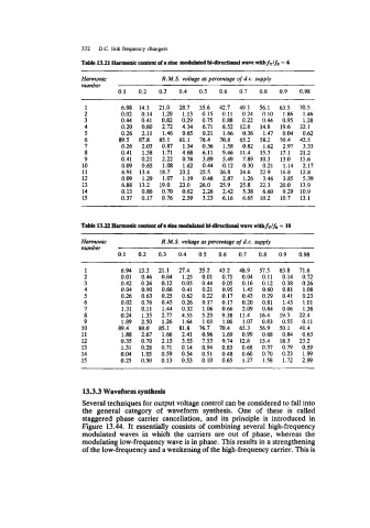
Table 13.21 Humonle content ofa alnc moddated M-dhrctiolld wave nlthfT/fs = 6
Harmonic R.M.S. voltage as percentage of d.c. supply
..U.WC.
0.1 0.2 0.3 0.4 0.5 0.6 0.7 0.8 0.9 0.98
~
1 6.98 14.1 21.0 28.7 35.6 42.7 49.1 56.1 63.5 70.5
2 0.02 0.14 1.29 1.13 0.15 0.11 0.24 0.10 1.86 1.46
3 0.44 0.41 0.82 0.29 0.75 0.88 0.22 0.44 0.95 1.28
4 0.20 0.80 2.72 4.34 6.71 8.52 12.6 14.8 19.6 22.1
5 0.26 2.11 1.46 0.65 0.21 1.66 0.36 1.47 0.04 0.62
6 89.5 87.8 85.1 81.1 76.4 70.8 65.2 58.2 50.4 42.5
7 0.26 2.05 0.87 1.34 0.36 1.58 0.82 1.62 2.97 3.33
8 0.41 1.58 1.71 4.68 6.11 9.46 11.4 15.3 17.1 21.2
9 0.41 0.21 2.22 0.78 3.89 5.49 7.89 10.3 13.0 15.6
10 0.09 0.65 1.08 1.62 0.44 0.12 0.30 0.21 1.14 2.17
11 6.91 13.4 18.7 23.2 25.5 26.8 24.6 22.9 16.8 12.8
12 0.09 1.29 1.07 1.19 0.48 2.87 1.26 3.46 3.85 5.39
13 6.88 13.2 19.0 23.0 26.0 25.9 25.8 22.3 20.0 13.9
14 0.13 0.86 0.70 0.62 2.26 2.42 5.38 6.60 9.29 10.9
15 0.37 0.17 0.76 2.59 3.23 6.16 6.65 10.2 10.7 13.1
Harmonic R.M.S. voltage as percentage of d.c. supply
number
0.1 0.2 0.3 0.4 0.5 0.6 0.7 0.8 0.9 0.98
1 6.94 13.3 21.1 27.4 35.2 43.2 48.9 57.5 63.8 71.6
2 0.01 0.46 0.84 1.25 0.01 0.75 0.04 0.11 0.14 0.72
3 0.42 0.26 0.12 0.05 0.44 0.05 0.16 0.12 0.38 0.26
4 0.04 0.90 0.66 0.41 0.21 0.95 1.45 0.60 0.81 1.08
5 0.26 0.63 0.25 0.62 0.22 0.17 0.43 0.29 0.41 0.23
6 0.02 0.76 0.45 0.26 0.17 0.17 0.20 0.81 1.45 1.01
7 1.31 0.11 1.44 0.32 1.06 0.66 2.09 0.84 0.06 1.38
8 0.24 1.35 2.77 4.55 5.23 9.38 11.4 16.4 19.3 22.4
9 1.89 2.50 1.26 1.64 1.03 1.00 1.07 0.83 0.55 0.11
10 89.4 88.0 85.1 81.8 76.7 70.4 65.3 56.9 50.1 41.4
11 1.88 2.67 1.66 2.41 O.% 1.69 0.99 0.68 0.84 0.63
12 0.35 0.70 2.15 3.55 7.53 9.74 12.8 15.4 18.3 23.2
13 1.31 0.28 0.71 0.14 0.94 0.83 0.68 0.37 0.79 0.59
14 0.04 1.05 0.59 0.54 0.51 0.48 0.60 0.70 0.23 1.99
15 0.25 0.50 0.13 0.53 0.10 0.65 1.27 1.58 1.72 2.99
13.3.3 Waveform synthesis
Several techniques for output voltage control can be considered to fall into
the general category of waveform synthesis. One of these is called
staggered phase carrier cancellation, and its principle is introduced in
Figure 13.44. It essentially consists of combining several high-frequency
modulated waves in which the carriers are out of phase, whereas the
modulating low-frequency wave is in phase. This results in a strengthening
of the low-frequency and a weakening of the high-frequency carrier. This is