
Page 344 - Power Electronics Handbook
P. 344
334 D.C. link frequency changers
sine wave inverters where the extra cost can be justified on account of the
reduction in harmonics, and therefore in the cost and size of the output
filter.
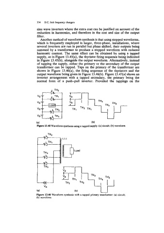
Another method of waveform synthesis is that using stepped waveforms,
which is frequently employed in larger, three-phase, installations, where
several inverters are run in parallel but phase shifted, their outputs being
summed by a transformer to produce a stepped waveform with reduced
harmonic content. The same effect can be obtained by using a tapped
supply, as in Figure 13.45(a), the thyristor firing sequence being indicated
in Figure 13.45(b), alongside the output waveform. Alternatively, instead
of tapping the supply, either the primary or the secondary of the output
transformer can be tapped. Taps on the primary of the transformer are
shown in Figure 13.46(a), the firing sequence of the thyristors and the
output waveform being given in Figure 13.46(b). Figure 13.47(a) shows an
inverter arrangement with a tapped secondary, the primary being the
normal form of a push-pull inverter. Provided the tappings on the
(a) (b)
15-45 Waveform synthesis using a tapped supply: (a) circuit; (b) waveform
JH2
N 1:l:l
&THl
N
d l
TH3
:I'C
VB
(a)
Figure 13.46 Waveform synthesis with a tapped primary transformer: (a) circuit;
(b) waveform